At Burning Amp this year, I brought with me a Zen variant I christened the "Half-Nelson", as the skeleton started out as an early member of the Zen series, with some bows and ribbons added.
The schematic is shown below. The LM317 is configured as a current source to bias both the input P-channel follower and the output P-channel FET. The current source is shunted by an RC network to provide opposite drive on the P-channel output to increase the possible outpout current. Bias was set at about 1A, and the pot is used to adjust the output centering. The amp was auditioned at Burning Amp, and did ok with a pair of Metronome speakers using an 8" hemp driver.
I've recently spun a second board with some improvements. Hopefully Ill have a chance to populate it over the holidays and bring it up, but I thought it would be good tio present the original concept. Pictures of the amp will follow.
Attachments
It hasn't seen an analyzer as of yet, though I guess I could haul it in to work after the holidays and subject it to the Audio Precision analyzer there - despite its nice rep, not the most user friendly of instruments. In initial simulations, the amp looked pretty Zen-ish in character, with low levels of higher harmonics and a similar gradual rise in distortion with output power. One thing I was proud of (and relieved about) is that the quiescent current is stable, even though I didn't put the bias FET and the upper output device near each other. The extra buffering makes the amp pretty fast - square wave rise time was only a few microseconds, and perfectly damped.
I sort of held off on this guy for a while after Burning Amp, as I've been messing with my "Shrine" tube amp and looking into making some more sensitiive speakers than the ones I have now. Also in the works is repackaging my preamp to include a JFET follower active crossover for biamping (and improve the cosmetics). The RIAA preamp uses a single ended JFET topology with a few special features, the result of a year or two dinking around with simple single-ended circuits using Amurrrican FETs. I'll be starting a thread on that one when I get the time.
Any way, I'll take a couple of pictures of the amp tomorrow and post them. If I have enough energy to drag it down to the basement, I'll also take some pictures of the square wave response. Have a nice Christmas....
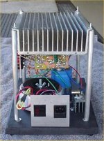
Attached is a photo of the Half Nelson piglet. Those who attended Burning Amp might have noticed it slouching on one of the side tables. The unusual manner of packaging was a matter of expedience, as I didn't have time to wrap any sheet metal around it before the big do. However, with a little tarting up, this kind of open packaging could be made to look pretty nice. Possible combinations: black anodized heatsink, input/power panels and toroid cover with oak base, or gold anodize with black piano finish base. If I can get the thing to perform to my satisfaction, maybe I'll get it some dress clothes
Attachments

My scope wouldn't save the waveforms (needs a new floppy drive), but output rise and fall times were ~ 1 usec.
For amusement and edification, I ran a set of simulations on the amp after tweaking the centering resistor values for higher impedance and gain. The JFET buffering allows the use of large values for centering resisors without affecting the bandwidth substantially. The first picture shows the altered schematic with quiescent bias values. Bias resistors were changed to reflect the on threshold voltages of the parts in the library. Gain is around 13X with the new values.
Attachments
I have been running this amp with a bench supply so far, as the line rejection is poor, so that your usual raw supply causes a lot of hum at the output. Next up is to try an LCLC filter, fed by a nice 44V Costwold toroid scored from Papa himself at Burning Amp. Maybe some of the magic will rub off.... Failing that, a drasic reduction in hum would be most welcome. I'll try a VGS multiplier if the inductive filter does not suffice.
Failing that, a drasic reduction in hum would be most welcome. I'll try a VGS multiplier if the inductive filter does not suffice.A revamped version of the Half Nelson (higher gain, more bias current) will slouch its way to Burning Amp this weekend. I want to go toe to toe with anyone industrious enough to have built a De-Lite in the year since Nelson introduced it at last BA. Consider the gauntlet thrown down. I just fired the beast in question up about 20 minutes ago, and it sounds pretty good, even before all the tweaking is done. My only question is, will Mark allow it in the hallowed Nelson room, seeing as it's at best a half-breed....
eh! Pass, inspired by Pass, they can all go to the Pass room, BUT there might be a different room that you prefer. There is a smaller one for low power stuff.., and maybe a less crowded one.. That way it can be heard a lot more..
The Half Nelson had its day in the rain at BA and acquitted itself rather well, despite having (get out the crosses and garlic) a dreaded electrolytic capacitor in series with its output. In all fairness, there was a good 3 uF polypropylene in parallel with it to help out. The changes I made in the gain/bias resistors since its first incarnation gave the amp more gain, so that it could be driven with a modest preamp. Adding an extra filter capacitor to the one already in the power supply, and slinging a capacitance multiplier between the two, had two beneficial effects: the nasty hum that first greeted me when I brought up this amp in 2007 is gone (!!!), and the multiplier acts as a slow-rise network, so there is no turn-on thump.
My only regret is that I did not cart it across the hall and ask that it be introduced to Nelson's $100 open baffles. I think the amp and speakers might have complemented one another.
Anyway, I like this amp enough so that I'll make a prettier version, though in its present state, it's ugly and eccentric enough to be rather likable. I think I'll keep the present "open tower" construction method, but with prettier heat sink and base, a toroid cover, neater wire dress, etc. I like eccentric stuff.
If there's interest, I'll post a more complete schematic of amp and power supply. I plan to use a higher supply voltage for the prettier version so that I can get some more output power. Back of the envelope calculations indicate that the amp is capable of about 9W/channel in its current incarnation with a 20V Antek toroidal transformer. The outputs are biased at 1A quiescent current. Since the amp can swing current in either direction, this means that it can source about 2A peak before it runs out of Class A. This says that I can get about 16W/side if I have enough voltage to back things up. I will need a supply voltage of at least 32V for that to happen, and my present supply is around 26. Make it 36V, then. I have some toroids that are capable of delivering a 40V supply, adding an extra resistor to the capacitance multiplier so that it can do a little regulation will get me a very clean 36V. Think it through. If you want more details, ask...
There was a lot of talk about the new Semisouth SiC devices at BA (a lot of it by Nelson). A Half-Nelson with one of the Semisouth fets in the bottom half of the output (replacing the IRFP240) might be interesting, especially as folks have already been talking about using current source loading for both the Ixys depeletion mode devices and the Semisouth. Food for thought, and grounds for further research...
Last edited:
This is the schematic of the current version of the Half Nelson that played at BA 2010. The original LM317 current source is replaced with a Supertex depletion mode fet (less problematic operation, higher impedance). The gain/bias resistors were changed from 47k, 1.5k and 10 k to 392k, 3.09k, and 115k. The pot is used to center the output at ~1/2 VCC. The ouput coupling capacitor was changed from 6800uF to 10000uF. I'll explain the circuit operation in another post - try to work it out for yourself in the mean time.
Attachments
Great to see you at BAF. Papa did let various people hook up to his system...next year bring it in its latest incarnation and I'm sure he will let you..
Already I'm saying "next year " 😉
And why not: BAF 5th year!
Mark
Already I'm saying "next year " 😉
And why not: BAF 5th year!
Mark
Last edited:
I had some other musings regarding simpler implementation for the Half-Nelson on the way home from the grocery store - it's a wonder I didn't space out and drive right off the road. I'll drop my ideas into a simulation and see what happens. I've already figured out a way to use the Semisouth depletion mode jfets with the Half-Nelson circuit. It requires a negative supply, but that's easy to arrange..
Here's the schematic for the power supply I'm currently using, thrown together out of items that were on hand. The electrolytic caps could obviously be 35V units for some space savings. Others might want to use an appropriate schottky rectifier (100V units would do it, 60V is cutting it too close) instead of the old Philips ultrafast dual rectifier that happened to be sitting in my parts bin. The RC snubber sitting across the rectifier was an old Rifa integrated RC snubber I had laying around - discrete parts would do just as well. The transformer in an old-style Antek toroid with tapped primary and dual secondaries, probably ~400 VA - again, something I had lying around. 400VA is overkill, as the amp only draws 2A from the supply. The darlington used in the capacitance multplier is an old Llambda TO-3 package device that was at hand - it fit nicely on a pre-drilled bracket and socket I already had prepared. A TO3-P package device like a TIP141 or TIP142 would no doubt work just as well. The darlington is mounted to the same heat sink as the amplifier output devices.
Attachments
I moved the Half-Nelson to the living room, where it booted out my "Gain Clown" composite chip amp for driving the mid-woofs of my biamped Parts Express Tri-Trix speakers - a nice change. Its needs a bit more power, but then I was dealing with Mussorgsky's "Pictures at an Exhibition" and Respighi's "Pines of Rome", both demanding pieces, especially at the end. It may stay in the living room for a while...
I just received some of the Ixys 6A depletion mode mosfets from Digikey. Since any Semisouth parts are months away for me, an obvious step would be to try out a couple of the Ixys parts in a variation on the Half-Nelson, replacing the IRFP240 in the output stage. More later, when I get a circuit roughed out.
- Home
- Amplifiers
- Pass Labs
- Half-Nelson Amp