It’s a single ended Class A with about 70mA bias current. It’s not meant for power hungry ortho dynamic phones. Minimum impedance is 50ohms, optimal is 250ohms. Let me run some sims to estimate output impedance.
@Vunce - FWIW, pretty much all I could use at home (small apartment) for a few years was HPs. I bought all kinds of stuff to fill the void of not having the loudspeaker system I left behind.  😀 HPs can be wonderful.
I travelled quite a lot , so tried all kinds of portables. Some great... sure. But, funnily enough it wasn't until I was able to start putting together a loudspeaker rig again ... and found that DIY could be fun... that I found XRK971s PCA.
I built 7 of the modified ones with bigger caps to have sufficient oooomph with 32 ohm planar cans. I've given 5 away, all to people that love music. Some are HP "enthusiasts", and they're all blown away.
I have 2 left, and they're not going anywhere. It's the only portable amp I use any more including the fancy commercial ones I bought. Plus, I admit I love the stares on planes when people see me plug HPs into an Altoids tin.
I can't wait to try the Hakuin with some Senns. (crossing fingers).

😀 HPs can be wonderful.I travelled quite a lot , so tried all kinds of portables. Some great... sure. But, funnily enough it wasn't until I was able to start putting together a loudspeaker rig again ... and found that DIY could be fun... that I found XRK971s PCA.
I built 7 of the modified ones with bigger caps to have sufficient oooomph with 32 ohm planar cans. I've given 5 away, all to people that love music. Some are HP "enthusiasts", and they're all blown away.
I have 2 left, and they're not going anywhere. It's the only portable amp I use any more including the fancy commercial ones I bought. Plus, I admit I love the stares on planes when people see me plug HPs into an Altoids tin.
I can't wait to try the Hakuin with some Senns. (crossing fingers).
IAIMH,
Thanks for the kind words! I get the same stares on my daily bus commute and it is a great conversation starter. You were able to drive 32ohm cans? What is the sensitivity of your cans? Maybe it can work there if sufficiently sensitive. I use on 16ohm IEM's but they are crazy sensitive at 114dB/mW so are no problem. That was kind of you to give away 5 amps.
I think you will like the Hakuin's sound - it is different with a BJT output vs a MOSFET.
Cheers,
X
XRK971 - My "daily driver" cans are Meze Classic. Per the mfr, they are 32 ohm, 103dB @1mW. I don't listen at ear-splitting levels. They're the cans I use most with the PCA. The IEMs I use the most are Beyer Xelento. Per mfr - 16 ohm, 110dB @1mW. To be fair - it does shine with 300 ohm Senns, but I don't travel with them.
More to the point, I was pleasingly surprised with the change to the caps you recommended with the "lower impedance" mods in the other thread.
More to the point, I was pleasingly surprised with the change to the caps you recommended with the "lower impedance" mods in the other thread.
I’ve heard the wooden Meze classics. They are nice for $100 cans. Wooden cups. They sound great on PCA. Never realized they were 32ohms. It’s because of the 101dB. I may have to get a set now.
I forgot what caps I recommended in the other thread. 🙂
I forgot what caps I recommended in the other thread. 🙂
It’s a single ended Class A with about 70mA bias current. It’s not meant for power hungry ortho dynamic phones. Minimum impedance is 50ohms, optimal is 250ohms. Let me run some sims to estimate output impedance.
"Output Impedance" is a high-NFB amplifier (though NFB declines at lower Z loads). Maybe under 1 Ohm. Plus the 1,000uFd cap.
Output drive ability is 5V on the up-swing and 13V/201r on the down-swing. *Clipping* levels:
Load - Output
200 - 6.48V (limited by 5V max upswing)
140 - 5V
100 - 4.32V
50 - 2.6V
32 - 1.8V
16 - 0.95V
600 - 20mW
200 - 63mW
140 - 87mW
100 - 93mW
50 - 69mW
32 - 51mW
16 - 28mW
50mW is plenty loud for most phones and most listeners, so it is ample. The few 600r phones around are pretty sensitive and 20mW should be ample. There were some crap 16r phones which will still be crap at 28mW. There are 16r earbuds derived from balanced-armature drivers which are EFFICIENT and even 1mW would be over-ample. Note that this is 0.126V at the phone and with gain of 4 only 0.032V at the input, a very low level. You may want a pad in front. You may even want a pad between "amp" and earbuds if amp hiss is audible. (The real deal for 16r receivers is 1.4V supply and no gain.)
Loads 32r and up allow significant NFB to reduce THD. THD won't be super low, but it won't be ugly distortion either.
X, do you have a .ASC file available to play with?
Sure, here you go...
Attachments
IAIMH reports that he got beautiful music from one channel of the amp. We are debugging now, but this is good progress.
Thanks IAIMH!
Thanks IAIMH!
FRESH NEWS!
I am a bit of a newbie... so I was extremely upset to have broken a trace while working on the prototype board. I know all the veterans out there know what it's like to release magic smoke, lift pads, mess up traces etc. But I was reaaaaaally P-O'ed when I got the amp almost to the finish line and lifted a pad and the trace along with it. Stupid me, rushing and not waiting for a proper part.
tl;dr - I built another board in no time flat (by my standards anyway) and it works 100%. 😀😀😀😀😀😀
Porn!

I also have the PSU section for the LiPo almost finished up. A few tiny things before I can test that. Ruler for scale. This stuff is weeeeeeeee tiny.

Happy Friday to all. Thanks again to xrk971 for the support!
Now... I have to bodge the bodge to fix the broken trace and troubleshoot the right channel on amp #1.
I am a bit of a newbie... so I was extremely upset to have broken a trace while working on the prototype board. I know all the veterans out there know what it's like to release magic smoke, lift pads, mess up traces etc. But I was reaaaaaally P-O'ed when I got the amp almost to the finish line and lifted a pad and the trace along with it. Stupid me, rushing and not waiting for a proper part.
tl;dr - I built another board in no time flat (by my standards anyway) and it works 100%. 😀😀😀😀😀😀
Porn!
I also have the PSU section for the LiPo almost finished up. A few tiny things before I can test that. Ruler for scale. This stuff is weeeeeeeee tiny.
Happy Friday to all. Thanks again to xrk971 for the support!
Now... I have to bodge the bodge to fix the broken trace and troubleshoot the right channel on amp #1.
IAIMH:
Very nice work!
Thank you so much for helping. DIY is a journey and you are going places!
This stuff is tiny to work with but ulitimately, it is not that hard once you are used to it, and is faster once you are practiced. Think of all the leads you did not have to bend 90 deg, and stick through a hole, and solder, and trim and all the board flipping back and forth.
Just apply solder paste, install little pieces using tweezers, hot plate or hot air or both, minor corrections on parts that stand up straight or otherwise misaligned, or apply some wick to clean up solder bridges, then done. No waste, no jar full of lead clippings, no dirty sponges in your solder iron base. 🙂
I am so glad that it sings - I hope it sounds great!
Cheers,
X
Last edited:
I also have the PSU section for the LiPo almost finished up. A few tiny things before I can test that. Ruler for scale. This stuff is weeeeeeeee tiny.
Happy Friday to all. Thanks again to xrk971 for the support!
Now... I have to bodge the bodge to fix the broken trace and troubleshoot the right channel on amp #1.
Excellent work IAIMH!!
Man, that’s a small board. I need a magnifier just to look at the picture

...And a Happy Friday back!
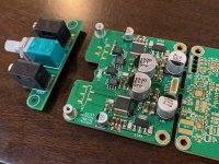
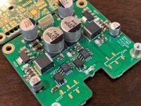
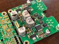
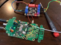
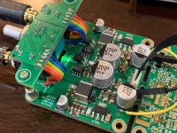
I couldn't let IAIMH have all the fun, buoyed by his success, I had to build my own Hakuin too. So just the amplifier section first. Everything soldered together nicely with paste and then hot plate to 135C and 300C hot air pencil on top to liquify the paste as needed. I did all parts except the big caps and the 6 pin connector first to allow even hot air heating of the small parts. Then I added the big caps and connector for a second round. This way, the small parts were ensured to be well wetted to prevent cold solder joints. Visually, the joints all look excellent.


Then I had to connect the volume pot and 3.5mm jack riser board to the main board but lacked the special Samtec surface mount 1.0mm pitch extenders (on order - IAIMH says they came all the way from Malaysia or something like that). In the meantime, I used ribbon cable to connect the two. Then used a small wire wrap wire to jumper pins 4 and 5 on the connector in order to enable the optoisolator coupled SSR's (these are normally controlled by a voltage supervisor and delay circuit to prevent turn-on/turn-off pops or thumps).

I then used a handy 5v to 24vdc DC-DC converter which feeds a pre-built TPS7A4xxx LDO set to 18.5v to power the amp. Jumpers were soldered to the leads on the 470uF rail smoothing caps (both as the supplies are separate on pins 1 and 6.
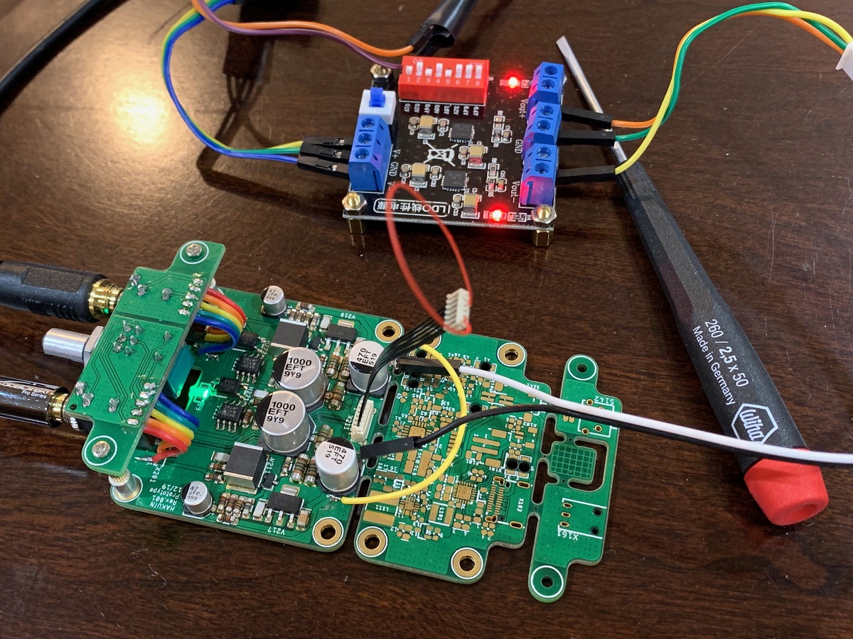
Turned it on, plugged in my SMSL Sanskrit 10 DAC as source and my DT-880 chrome SE 250ohm headphones and I have glorious music! It all works first time. Solid layout by JPS64!

The amp sounds great. Only had a chance to listen to a few songs but it is very nice. Super quiet (silent) when source is off.
We might have to play with the DC setpoints on the resistors a bit as the bias current across the 51R resistor is measuring only 40mA vs the 70mA design point. This is to be expected as the models of the JFET and BJT are not exact and there is variability in the parts. The bias currents are balanced though.
Then I had to connect the volume pot and 3.5mm jack riser board to the main board but lacked the special Samtec surface mount 1.0mm pitch extenders (on order - IAIMH says they came all the way from Malaysia or something like that). In the meantime, I used ribbon cable to connect the two. Then used a small wire wrap wire to jumper pins 4 and 5 on the connector in order to enable the optoisolator coupled SSR's (these are normally controlled by a voltage supervisor and delay circuit to prevent turn-on/turn-off pops or thumps).
I then used a handy 5v to 24vdc DC-DC converter which feeds a pre-built TPS7A4xxx LDO set to 18.5v to power the amp. Jumpers were soldered to the leads on the 470uF rail smoothing caps (both as the supplies are separate on pins 1 and 6.
Turned it on, plugged in my SMSL Sanskrit 10 DAC as source and my DT-880 chrome SE 250ohm headphones and I have glorious music! It all works first time. Solid layout by JPS64!
The amp sounds great. Only had a chance to listen to a few songs but it is very nice. Super quiet (silent) when source is off.
We might have to play with the DC setpoints on the resistors a bit as the bias current across the 51R resistor is measuring only 40mA vs the 70mA design point. This is to be expected as the models of the JFET and BJT are not exact and there is variability in the parts. The bias currents are balanced though.
Attachments
@XRK971 -
Congratulations!!!! That looks fabulous. 😀 😀 😀
Looking at your work... I maaaaaaaaaay have a tendency to use too much paste. 😉
Congratulations!!!! That looks fabulous. 😀 😀 😀
Looking at your work... I maaaaaaaaaay have a tendency to use too much paste. 😉
Yes, be very frugal with the solder paste - it looks neater and less chance of a solder bridge or short. You have to use both a hot plate from bottom and hot air from the top for the joints to wet and flow evenly.
If you apply to much paste by accident, just wipe up the offending pads with a cotton swab with alcohol and start over.
If you apply to much paste by accident, just wipe up the offending pads with a cotton swab with alcohol and start over.
I think I know why my bias current was low: I forgot that I only had a small 6v low amperage wall wart power the DC step up so it was current limited and voltage dropped to 10v. IAIMH’s amp is hitting all the DC setpoints let the simulation - about 70mA bias current.
Yep, replaced wall wart with a 12v 2000mA supply and now have steady 18.5v rails. Bias current is 75mA, almost exact value as predicted by LTspice simulation. Kind of lucky I suppose.