...confusion stems from the manual going from 40dB to 50db one also installs a resistor into R23 which also changes the cartridge loading from 47K to who ......
A 40dB RIAA preamp is almost certainly "Pickering" moving magnet 47k loading.
50dB and 60dB are mostly low-impedance moving coil. These may or may not benefit from a low impedance loading. The custom of using transformers implies a lower impedance though a high step-up, so I guess the carts were mostly designed along low-Z loading. And Jim's table gives the most likely values of the loading resistors.
But part of "47k" is really cable and tube capacitance. When we go lower Z cartridge the capacitance matters much less, the resonance tends to be supersonic, the loading not real critical. Obviously if your car specs have a number, use that.
A very quick and inexpensive "hey let's give THIS a try" experiment, is to install an LCLC filter in series between an SMPS wall-wart, and the audio gear it powers. You just plug the barrel jacks together, don't even need to open the chassis. Several diyAudio members have reported great results when doing this with the Korg NuTube B1 linestage kit from the diyAudio store.
PO89ZB , an inline DC filter for SMPS wall warts . Preamps, HPA, Korg NuTube, etc
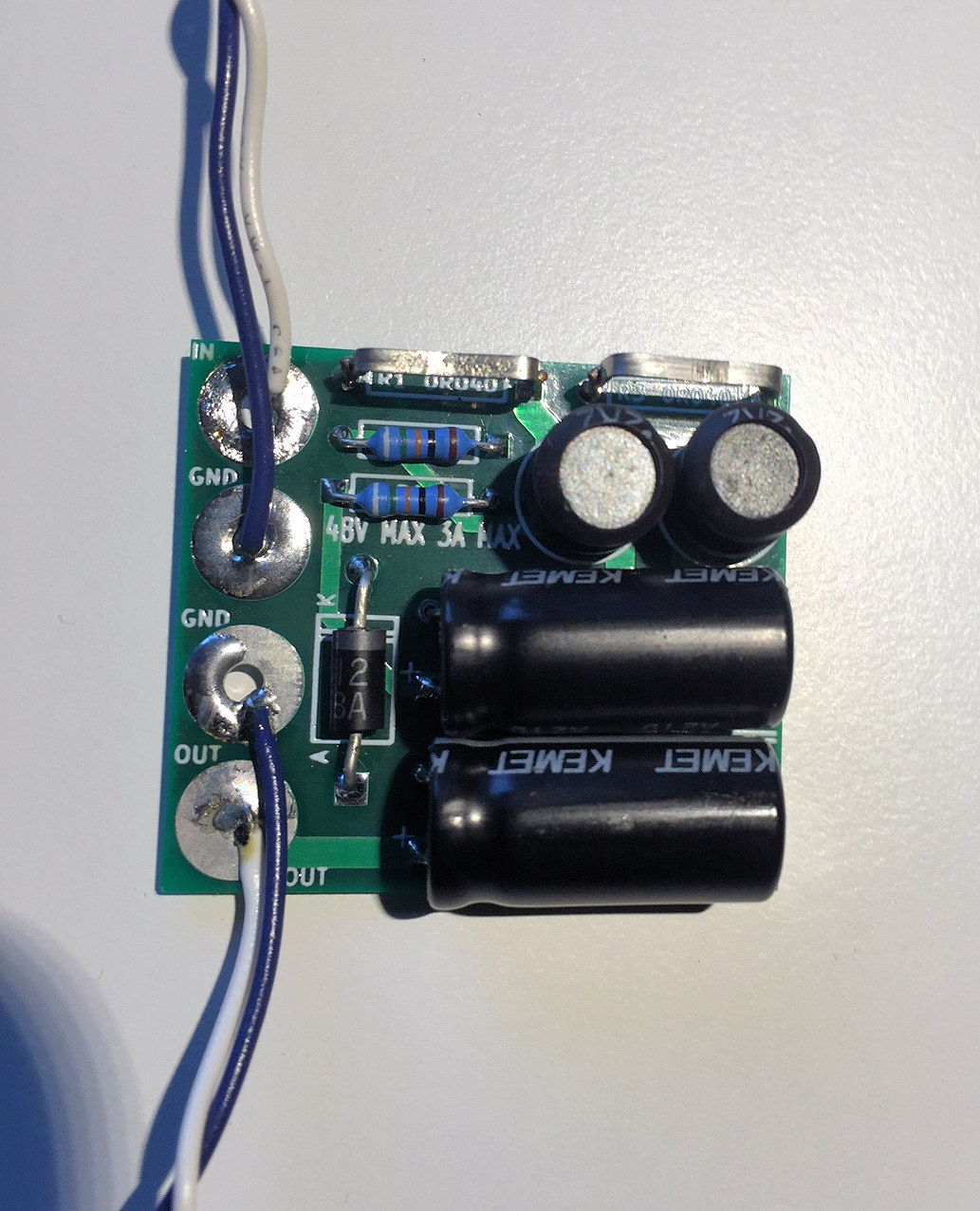
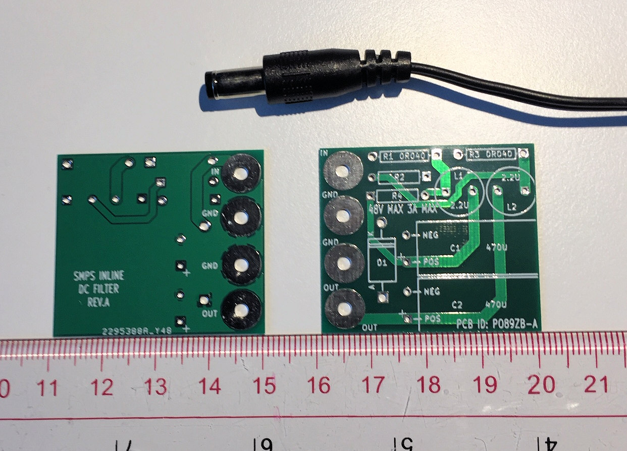
PO89ZB , an inline DC filter for SMPS wall warts . Preamps, HPA, Korg NuTube, etc
I would think Hagerman's new Trumpet phono stage sounds pretty special! 🙂
And it is lot cheaper than it was, last time I looked.
Andy
And it is lot cheaper than it was, last time I looked.
Andy
I'll be interested to hear if you find the linear psu improves the preamp.
--
Seems the “Hag” picks up interference...regardless of supply so hard to determine. If I wrap my hands around it, it gets quieter but doesn’t go away....hummmm. Back to the shelf!
That's odd. Mine doesn't. My system is totally upset by the presence of a Raspberry Pi—weird robot gurgling in both channels on all inputs (not just the phono). If I power off the Rpi it's nice and quiet, even with lowly OPA2134 op amps. Hum is only audible if I stick my ear in the woofer.
What kind of case do you have yours in? Audio pcb and psu in one chassis? Mine is connected by an umbilical, both pcbs in black steel enclosures.
Oh well. Sorry to hear yours hums. That would be a deal-breaker.
--
What kind of case do you have yours in? Audio pcb and psu in one chassis? Mine is connected by an umbilical, both pcbs in black steel enclosures.
Oh well. Sorry to hear yours hums. That would be a deal-breaker.
--
In my DIY-Bugle I used 681R for R3/R8 to get 50 dB gain. I am also using it with a Denon DL-110. It is a high ouput mc, you usually just load it with 47k (R23). It's impedance is 160 Ohms, so with the 10x rule a load from 1k6 on up should be fine.
That's odd. Mine doesn't. My system is totally upset by the presence of a Raspberry Pi—weird robot gurgling in both channels on all inputs (not just the phono). If I power off the Rpi it's nice and quiet, even with lowly OPA2134 op amps. Hum is only audible if I stick my ear in the woofer.
--
I built a preamp / input selector etc. with the Bugle as the phono stage, also including a Raspberry Pi for streaming (Roon endpoint / Moode). I found that if I used the same power supply for the RPi and analog circuits, a lot of noise was injected into the analog circuitry. My solution was four separate power supplies:
- +/- 15V for analog circuits
- 5V for source switching relays
- Separate 5V wall wart for RPi
- Separate wall wart for the Bugle.
That's odd. Mine doesn't. My system is totally upset by the presence of a Raspberry Pi—weird robot gurgling in both channels on all inputs (not just the phono). If I power off the Rpi it's nice and quiet, even with lowly OPA2134 op amps. Hum is only audible if I stick my ear in the woofer.
What kind of case do you have yours in? Audio pcb and psu in one chassis? Mine is connected by an umbilical, both pcbs in black steel enclosures.
Oh well. Sorry to hear yours hums. That would be a deal-breaker.
--
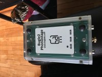
Post 182....original case
Ah, translucent plastic case = no shielding
Maybe if it was in a metal, shielded enclosure, with the signal grounded to chassis at the input?
Maybe if it was in a metal, shielded enclosure, with the signal grounded to chassis at the input?
I built a preamp / input selector etc. with the Bugle as the phono stage, also including a Raspberry Pi for streaming (Roon endpoint / Moode). I found that if I used the same power supply for the RPi and analog circuits, a lot of noise was injected into the analog circuitry. My solution was four separate power supplies:
I put the first two in a box with a switch (which I never turn off), and the other two on a power strip. This solved the noise injection problem.
- +/- 15V for analog circuits
- 5V for source switching relays
- Separate 5V wall wart for RPi
- Separate wall wart for the Bugle.
I don't have a relay switch for input selector. I'm using a standard rotary mechanical switch.
I'm using an Intact Audio autoformer (inductive) volume control.
I have a separate 5V DC SMPS for the RPi.
The DAC (Topping D10) uses USB bus power from the RPi, but disconnecting the DAC does not cause the noise to stop (thus indicating that the noise is coming from the RPi or its PSU).
I have a separate linear +/-15VDC supply for the Bugle.
I have JBL LSR305 speakers, which are self-powered.
The could be ground loops in my AC wiring. I have to unplug everything and reinstall in a more orderly fashion. I can't get audio from my TV using anything but its HDMI connection to a separate AV receiver, due to really loud hum from the TV's analog or coax S/PDIF outputs. It's part of a ground loop somewhere.
--
Ah, translucent plastic case = no shielding
Maybe if it was in a metal, shielded enclosure, with the signal grounded to chassis at the input?
I’m on it! Thanks
I am also using it with a Denon DL-110. It is a high ouput mc, you usually just load it with 47k (R23).
Yes, that's the "generally accepted" wisdom - but I suggest it may not actually deliver the best sound. After all - there are MMs (or rather MIs, as I'm referring to the Grado wood-bodied carts) which sound their best at 33-35K.
It's impedance is 160 Ohms, so with the 10x rule a load from 1k6 on up should be fine.
My own view is that 10x - 100x coil impedance is the useful loading range.
Why don't you try your DL-110 loaded at 16K ... to see what it sounds like? 🙂 (For the experiment, you'd need to employ RCA 'T' connectors and a pair of 22K-loaded RCA plugs ... which will give you 15K. Then you can change the load on the PCB, if it sounds better than 47K - and get rid of the 'T' connectors.)
Andy
Last edited:
Ah, translucent plastic case = no shielding
Maybe if it was in a metal, shielded enclosure, with the signal grounded to chassis at the input?
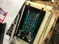
Better? Need to add ground stud, then ground case.
Attachments
Ah, translucent plastic case = no shielding
Absolutely! One has to wonder why Jim decided to reduce mfg cost so much that he used a plastic case? 🙁
Maybe if it was in a metal, shielded enclosure, with the signal grounded to chassis at the input?
Metal case, yes - which is grounded - would solve the problem.
But I wouldn't connect input signal ground to the case - I would use an earth terminal on the metal case and connect this to the earth terminal on another component (like a preamp) which has a 3-wire mains cord ... having the earth pin on the IEC input socket (or the earth wire in the mains cord) connected to the (metal) chassis.
Andy
- Home
- Source & Line
- Analogue Source
- Hagerman Bugle 2