Take your time and follow the instructions and you should be fine.
His kits are pretty good, and contain everything you need including good solder.
Don't use any unknown,leftover or poor quality solder that might be kicking around, as that can cause you endless endless grief, especially if it turns out to be acid core 🙁
His instructions are good and I found him very open to answering questions I had.
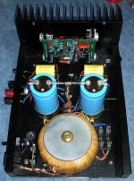
Btw, here are pics of his DH200 boards in my mono amps.
I could have went with either model, but preferred to use up my DH200 heat sinks.
His kits are pretty good, and contain everything you need including good solder.
Don't use any unknown,leftover or poor quality solder that might be kicking around, as that can cause you endless endless grief, especially if it turns out to be acid core 🙁
His instructions are good and I found him very open to answering questions I had.
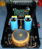
Btw, here are pics of his DH200 boards in my mono amps.
I could have went with either model, but preferred to use up my DH200 heat sinks.
Attachments
Looking goood...
Do you think can be added 3 pairs of output transistors (so total of 4 pairs) to increase power output to 350W/8ohms??
Do you think can be added 3 pairs of output transistors (so total of 4 pairs) to increase power output to 350W/8ohms??
That never occurred to me, as the stereo or mono Hafler based versions have plenty enough power for my mid high speakers, so not relevant in my application.
For my bass columns I have another workhorse amp to feed them what they need.
If you go back in this thread though, some have added an extra pair of output transistors to each side and did report success with that upgrade.
There is plenty of good info/mods in this thread if you take the time to go through it all, much of it by Fab.
"Do you think can be added 3 pairs of output transistors (so total of 4 pairs) to increase power output to 350W/8ohms?? "
Sure, that's what a bridged DH220 puts out.
Sure, that's what a bridged DH220 puts out.
To increase output power, supply voltage must also be increased. Bridging uses two channels that simultaneously swing to their voltage rails. There are hazards to either approach that must be addressed.
The Hafler XL600 did 350W/8Ω on 4 pair with a high-voltage tier of about ±100V for the front end, about ±93V on the outputs.
Had to use the 200V/8A outputs too.
Had to use the 200V/8A outputs too.
Sometimes the amount of extra power you get is eaten by the lowered efficiency of hotter voice coils. Chasing that little extra really doesn't buy you a great deal in real terms either.
-Chris
-Chris
just curious if any of you hafler owners saw bob cordell's talk on hafler mods from BA2016 (available on youtube)?
Any thoughts or are any of you working on it in your secret labs?
🙂
mlloyd1
I am also curious, if anyone works already in secret labs on Bobs new Hafler design.
Just working on a rebuild of two PC-19C pcbs for a Hafler DH-220 with new parts. A nice way would be to create designs for the orginal pcb size of the DH-220 pcbs (or even on the PC-25D for the DH-120) and using the original frontend as mentioned by Bob.
On the other hand would be interesting for a complete new PCB based on the 2sk1058/2SJ162 and adequates (Exicon, etc) frontend, since these lateral Fets are still in production.
Any more news to that project, beside the already published, like Bob Cordell's presentation at BAF2016 ??
I suppose that a survey for a possible group buy would motivate a dedicated pcb from Bob Cordell new schematic....I am also curious, if anyone works already in secret labs on Bobs new Hafler design.
Just working on a rebuild of two PC-19C pcbs for a Hafler DH-220 with new parts. A nice way would be to create designs for the orginal pcb size of the DH-220 pcbs (or even on the PC-25D for the DH-120) and using the original frontend as mentioned by Bob.
On the other hand would be interesting for a complete new PCB based on the 2sk1058/2SJ162 and adequates (Exicon, etc) frontend, since these lateral Fets are still in production.
Any more news to that project, beside the already published, like Bob Cordell's presentation at BAF2016 ??
Bob added resistors at the source of the p channel to adjust for transconductance difference the P and n channel but because of the wide variation of the IDss parameter of input dual jfet one would also need to add some potentiometer. What is more tricky is to obtain a similar operating point of the jfet from one amp to the other unless be able to select jfet for spefific IDss range....
Fab
Last edited:
We shall see what Bob has to say about grading/matching of complementary jfet pairs. There is no grading of Idss in the parts specs, they show a wide variation.
The source R is used for lsj689 to match the transconductance with the lsk489. Bob wrote the lsj689 app note, read it if you need to find out more.
I assume it will be a cascode ips design, since Vds max is 50-60V for the parts.
I/we do not know the details of Bob's design, he could have very well used a servo for DC offset control.
be patent, wait for the book to come out, showing the details.
We shall see what Bob has to say about grading/matching of complementary jfet pairs. There is no grading of Idss in the parts specs, they show a wide variation.
The source R is used for lsj689 to match the transconductance with the lsk489. Bob wrote the lsj689 app note, read it if you need to find out more.
I assume it will be a cascode ips design, since Vds max is 50-60V for the parts.
I/we do not know the details of Bob's design, he could have very well used a servo for DC offset control.
be patent, wait for the book to come out, showing the details.
Did you watch here at about 39:00?
https://www.youtube.com/watch?v=V7-27fDgqco&t=1300s
Bob discusses it and obviously if the duals are matched and the sources of the top and
bottom pairs are connected together the total source current has to be the same.
Bob says to adjust the R between them to set the operating point. I think that what
would be seen in operation is that the Vsource for the top pair relative to ground will
not compliment the Vsource for the bottom pair and rather they adjust as needed for
equal currents since the source currents are forced by design to match.
i'll put on my prognosticator hat for a moment and wager that within 2 days after bob's schematic for the updated hafler appears in this thread, alexmm or someone will have a nice board layout.
🙂
mlloyd1
🙂
mlloyd1
someplace around here, EUVL posted some notes about a nice trick to improve the resulting match between njfets and pjfets.
i'll post a link when i find it - it was good reading (as is usual from Patrick).
mlloyd1
i'll post a link when i find it - it was good reading (as is usual from Patrick).
mlloyd1
someplace around here, EUVL posted some notes about a nice trick to improve the resulting match between njfets and pjfets.
i'll post a link when i find it - it was good reading (as is usual from Patrick).
mlloyd1
Bob used a touch of degeneration on the bottom pair and none on the upper in his
talk, was EUVL's method different?
Yes, I watched it again to refresh, so the circuit is basically there at the 49:00 min mark on. At the 54:00 min mark he shows the DC servo injection point. 57:00 shows the CFP bias and gate protection. So the design is basically there for you right now. No excuses now to make your own.
good luck getting alexmm to make you a pcb.
good luck getting alexmm to make you a pcb.
hi pete;
similar principle. patrick had nice pdf write-up on testing that might help explain the concept more for folks that want to make changes or understand more about the "whys".
mlloyd1
similar principle. patrick had nice pdf write-up on testing that might help explain the concept more for folks that want to make changes or understand more about the "whys".
mlloyd1
I assume that if you guys are expecting someone else to make the pcb, then either you do not know how to or are not interested in doing the work, cheaper to get someone else to do it for you 🙂
If you do not know how, I can help you out. I have been playing around with diptrace, you should give it a try, that way we can share the design. I usually use orcad but that is a bit harder to figure out, unless you are really interested in pcb design.
It is all learning curve, but if people help,teach it is a lot less painful.
So to start, ones needs a mech data/drawing, showing pcb size, tooling/mounting hole sizes,locations, connector locations.
I do not have a unit, to do it myself. I looked at the dh-220 docs, it is not a real big job. A big part is getting the libraries all together. I myself would do it in smt for the most part, it saves so much space, 2-sided pcb is imperative for smt.
Wouldn't Bob be grateful, if someone does him up a board to go with his design.
- Home
- Amplifiers
- Solid State
- Hafler DH-200/220 Mods