Here is an update on my voltage regulator problem:
Apparently, a surge did blow through the transistors (7 out of the 13 on the board when pulled and tested were broken).
At jakinnj's suggestion, (see post #283) I replaced the ordinary diode (1n4003) that was across each regulator (LM3x7) with a 33 volt zener, and connected the regulator to a functioning PC19 board in the amp. After several on/off cycles (with full warm-up before turning off) all seemed well (stable zero dc offset, bias current).
The amp played music as usual, except some audible buzz which sounded like a bad rectifier. One rail had 0.03 volts of ripple, compared to 0.003 on the other, and I traced this to the bridge rectifier on the VR. This condition existed before I ever hooked it up to the amp. (see post #271).
After I replace the rectifiers with better ones, I'll do a sound comparison.
Thanks for all of the help!
Hafler XL-280 - magic smoke got out
My XL-280 decided to release some magic smoke this evening. I opened it and found the C201 and C202 (470 mfd, 100v) electrolytic caps in the center of the PC-41A board blew their tops. Replacing these two caps isn't difficult for me. Figuring out what (besides their old age and many months of inactivity) may have caused them to blow is beyond my meager
  skills.
As long as I've got the board unscrewed from the main caps (they all look fine at the moment) should I just go ahead and replace the four 1N4003 diodes and the 1KV disk cap on the board as well? Finally, what specific caps (and diodes) would you recommend as replacements? Mouser stocks plenty, and I'm guessing anything of similar size and rating would work.
Thank you in advance!
My XL-280 decided to release some magic smoke
this evening. I opened it and found the C201 and C202 (470 mfd, 100v) electrolytic caps in the center of the PC-41A board blew their tops. Replacing these two caps isn't difficult for me. Figuring out what (besides their old age and many months of inactivity) may have caused them to blow is beyond my meager skills. As long as I've got the board unscrewed from the main caps (they all look fine at the moment) should I just go ahead and replace the four 1N4003 diodes and the 1KV disk cap on the board as well? Finally, what specific caps (and diodes) would you recommend as replacements? Mouser stocks plenty, and I'm guessing anything of similar size and rating would work.
Thank you in advance!
Figuring out what (besides their old age and many months of inactivity) may have caused them to blow is beyond my meager skills.
An older amp such as yours that has sat inactive for many months should be started slowly with a Variac else some of the old electrolytic caps may fail.
Chances are that you only need to replace these caps and that nothing else was damaged. Do you see any signs of scorching on the mounting board?
You could replace the little caps and try your amp. Do you know how to put a light bulb in series with the incoming AC to reduce input voltage? Can you borrow a Variac?
Replacement caps should be similar to those removed. Select low ESR and higher temp ratings if possible, as well as the same voltage and capacitance rating.
Dick, thank you  for your quick response.
Fortunately there are no scorch marks anywhere on the power board or other components, so nothing else appears to have overheated. I've ordered some Nichicon UVR2A471MHD caps from Mouser this morning, so I'll get those installed as soon as they arrive. I don't have a variac, but I can definitely wire a light socket in line with the hot leg of a power cord and start with a low wattage bulb, eventually graduating up to a 120 or 150 watt bulb. I'm just glad the four big 7800 uFD caps weren't the ones that decided to let go of their magic smoke.
for your quick response. Fortunately there are no scorch marks anywhere on the power board or other components, so nothing else appears to have overheated. I've ordered some Nichicon UVR2A471MHD caps from Mouser this morning, so I'll get those installed as soon as they arrive. I don't have a variac, but I can definitely wire a light socket in line with the hot leg of a power cord and start with a low wattage bulb, eventually graduating up to a 120 or 150 watt bulb. I'm just glad the four big
7800 uFD caps weren't the ones that decided to let go of their magic smoke.It seems you are on the correct path. Do you have a VOM? After you remove the suspect caps you could remove the two rail fuses in each channel's PCB and measure the voltage that comes from the 4 small diodes, at the point where they used to connect to the 470 uF caps. If you get a reading of ~75 VDC your diode bridge is OK. The reading will be a little high because there is no load and no filter caps connected. But, this will help assure you that connecting the new caps is a wise move. Then, when this is done and the new caps installed, you can gently restart the circuit using light bulbs. Then, you should verify a reading of ~ ±70 VDC.
If you do this be very careful of the large PS caps as they will still have a full charge as there is no load on them with the rail fuses removed. You can discharge them by carefully applying a 3000 ohm 5 or 10 watt resistor to bleed away their charge. In fact, these resistors could be clipped to each of the 4 large PS caps before testing. PS caps can pack a lethal charge so keep one hand in your pocket when messing around with this part of the circuit.
A bleeder resistor for your amp, if permanently installed in parallel to each large PS cap, should be around 6800 ohms in value. The lower value I suggested is to speed up discharge time but they will get hot if left on for any length of time.
I'm an infrequent amateur who picked up a used Variac on an eBay auction 6 years ago. It was one of the best purchases I ever made. It was less than $50 for a 5 amp Variac and is now installed in an old AT computer power supply case (the large old version) complete with a pilot lamp and ON/OFF switch. I never apply full power to an old device or to one that has been in storage for any length of time or to a device to which I have made repairs or changes. You won't be sorry to get one. I am told by experts here that a Variac with a rating as low as 3 amps is sufficient for the testing of most solid state amps.
Nichicon is a good name for caps. Good luck.
Re: Hafler XL-280 - magic smoke got out
sorry to hear that; nothing like the sad smell of magic smoke drifting away. hopefully, the JFETs on the driver board are undamaged; they are virtually impossible to replace. XL-280 is a nice amp.
if you replace the caps, use a series light bulb or a variac to limit current in case the fault is still present. btw, i have had old caps that shorted as a failure mode, just not two at the same time on the same product ...
mlloyd1
edit: oops sorry, guess i should have read before posting embarrasment 😱
keith721 said:My XL-280 decided to release some magic smoke
Dick: I have a digital multimeter, so I can definitely pull fuses and check voltages before proceeding. My step-father was an old-school TV repair tech and taught me how dangerous (and fun 😀 ) power capacitors and flyback transformers could be when I was still a teenager. When you suggest bleeder resistors in parallel with each of the big capacitors, I understand they should be connected with one leg attached to each of the two screw-on terminals atop each cap. Is this correct?
mlloyd1: My wife had never heard of the magic smoke inside electronic gear. I explained how hard it was to pack so much smoke inside all those tiny components, then having to add more smoke using your soldering iron to make it all work together. 😉
I figure if those two caps were that far gone, I'd just as well have found out sooner, rather than later. Now I just need to be more careful with the four big ones. I suspect they wouldn't be so inexpensive to replace, exact size replacements couldn't be found, and they'd release a heckuva lot more smoke.
Thank you both for your suggestions.
mlloyd1: My wife had never heard of the magic smoke inside electronic gear. I explained how hard it was to pack so much smoke inside all those tiny components, then having to add more smoke using your soldering iron to make it all work together. 😉
I figure if those two caps were that far gone, I'd just as well have found out sooner, rather than later. Now I just need to be more careful with the four big ones. I suspect they wouldn't be so inexpensive to replace, exact size replacements couldn't be found, and they'd release a heckuva lot
more smoke.Thank you both for your suggestions.
Just an update
Nichicon caps arrived Thursday and were installed Friday night. The second XL-280 amp used to verify the power supply wires were reattached correctly had some poor solder joints, so those got touched up while the iron was hot. It's Saturday morning and the first amp has been powered up with a 25 watt bulb in-line for an hour with no sign of magic smoke. How long should it idle at 25 watts before moving up to a 60 watt bulb? (I'm guessing at least another hour or two.)
Nichicon caps arrived Thursday and were installed Friday night. The second XL-280 amp used to verify the power supply wires were reattached correctly had some poor solder joints, so those got touched up while the iron was hot. It's Saturday morning and the first amp has been powered up with a 25 watt bulb in-line for an hour with
no sign of magic smoke. How long should it idle at 25 watts before moving up to a 60 watt bulb? (I'm guessing at least another hour or two.)The 470 uF (new) caps you installed don't require an extensive break in or forming time. You can put on the 60 watt bulb for a few minutes, and then go it alone with no bulbs.
Have you checked voltages? Are they OK? Have you checked DC offset?
Let's hope your amp repair was as simple as replacing two small old caps
Have you checked voltages? Are they OK? Have you checked DC offset?
Let's hope your amp repair was as simple as replacing two small old caps
Re: Just an update
The idle current will wander around a bit for the first couple of hours, you can periodically check it, write the number down and keep it in your notebook. :burn:
PS it's always a good idea to keep a notebook.
keith721 said:Nichicon caps arrived Thursday and were installed Friday night. The second XL-280 amp used to verify the power supply wires were reattached correctly had some poor solder joints, so those got touched up while the iron was hot. It's Saturday morning and the first amp has been powered up with a 25 watt bulb in-line for an hour with
The idle current will wander around a bit for the first couple of hours, you can periodically check it, write the number down and keep it in your notebook. :burn:
PS it's always a good idea to keep a notebook.
I let it go for three hours at each of 25 and 60 watts. After an hour at 100 watts I checked all the voltages across the top of the PC-41A board. Everything EXCEPT the left channel B--  was looking okay. Since I didn't rework any of the solder points near the diode bridge, it's not likely a cold solder joint. I probably should have just gone ahead and replaced all the 1N4003 rectifier diodes the first time around. Fortunately, they're cheap enough at the RatShack around the corner... 🙄
was looking okay. Since I didn't rework any of the solder points near the diode bridge, it's not likely a cold solder joint. I probably should have just gone ahead and replaced all the 1N4003 rectifier diodes the first time around. Fortunately, they're cheap enough at the RatShack around the corner... 🙄Which PS for the left channel are you referring to? Are you referring to the voltage that comes from the large PS filter caps that run the output MOSFETs, or the PS that runs the PCBs?
Each MOSFET PS is separate from the other channel. The two pairs of the large PS filter caps present a sort of dual mono to the MOSFETs. YOu could have one PS for one channel's output MOSFETs at a different voltage level than the other channel.
The PS that runs the PCBs is NOT dual mono. It is a single PS that runs both PCBs. Therefore, if the voltages to one PCB are OK they should also be OK for the other channel. IF not you have a problem with wiring not diodes. The voltages presented to both PCBs should be identical because they both come from the same PS.
Dick: Thank you for helping me with this. I installed $1.40 worth of four new 1N4003 diodes this afternoon and double-checked all the soldering on the PC-41 power supply board. I've now got Left B-- voltage the same as the Right B--, so whatever was wrong yesterday seems fixed 😀 today.
I pulled all four circuit board fuses and am now starting it with the 25 watt bulb again, but only for thirty minutes. If everything holds steady with the 60, 100, 150, and 200 watt bulbs, then I'll re-install the fuses, check the final voltages, and give it a tryout later tonight.
I pulled all four circuit board fuses and am now starting it with the 25 watt bulb again, but only for thirty minutes. If everything holds steady
with the 60, 100, 150, and 200 watt bulbs, then I'll re-install the fuses, check the final voltages, and give it a tryout later tonight.Houston, we have liftoff!!
Thank you Dick for patiently guiding me. I re-inserted the four PCB fuses, connected test speakers and gently fed the amp Smokin'
  from Boston's debut album. I was rewarded with high quality sound once again, so I let it finish playing at very low volume with the test speakers. I've now switched over to the front main speakers and raised the volume just a little (so as not to disturb the neighbors this early on Sunday evening.) It's great to have this amp running again, and it sounds a heckuva lot better than either of my two recent-issue JVC receivers.
Thank you Dick
for patiently guiding me. I re-inserted the four PCB fuses, connected test speakers and gently fed the amp Smokin' from Boston's debut album. I was rewarded with high quality sound once again, so I let it finish playing at very low volume with the test speakers. I've now switched over to the front main speakers and raised the volume just a little (so as not to disturb the neighbors this early on Sunday evening.) It's great to have this amp running again, and it sounds a heckuva lot better than either of my two recent-issue JVC receivers.I also love Hafler amps. Currently am listening to 3 of them in my 5.1 home theater. In the main music room at the rear of the house are two more Haflers. Life is good -- especially when they work 
I would not own amp amp without a schematic, pictures of it layout and PCB, and list of parts. The vintage hafler amps have all of this.
I would not own amp amp without a schematic, pictures of it layout and PCB, and list of parts. The vintage hafler amps have all of this.
So, now that one's working....
There's another XL-280 I acquired recently and I was checking it out tonight before connecting it. I took it gently on this one, using the light bulbs until all the voltages on the power supply board were steady.
I'm a bit concerned about the left channel in this amp. This is the PC-40D board that had loose wiring when I received it. After it was powered off I plugged in my speakers and the left channel generated some noise. The right channel didn't. I'd guess there might be some DC leakage through the left channel, but I'm not certain how to verify this. Is it as simple as putting my meter across the speaker outputs when there's no input signal? Or should I remove the line fuses from the card and take voltage measurements around the board first?
Thanks in advance 🙂
Typically DC offset is rather stable in value as measured across the speaker outputs. It should be less than 50 mV. If you are getting noise you can do several things.
First, run the amp on the lowest voltage possible (with your lightbulbs). Attach a junk speaker and listen as you tap various parts of the circuit for something loose that makes the intermittant noise you hear.
If that fails you can try some heat and cold applied to parts on the PCB while listening for a change in noise as a function of temperature change.
If this does not help isolate some fault condition you are stuck without a signal generator and o'scope.
You can measure voltages on the PCB and compare the voltage on the good channel with that on the bad channel, when measured at the same spot and referenced to ground (the connection between the caps in the PS). PCB trouble shooting can be done with the rail fuses pulled to protect the output stage.
Let's hope someone smarter than me chimes in to make suggestions.
Dick
2SK134 / 2SJ49, PC6 boards on eBay
Search eBay for seller name 'cdsherman' (NOT my auction.) He's selling four separate PC6 boards and has more Hitachi MOSFETS. They appear to be stamped with Hafler's matching numbers.
Search eBay for seller name 'cdsherman' (NOT my auction.) He's selling four separate PC6 boards and has more Hitachi MOSFETS. They appear to be stamped with Hafler's matching numbers.
Be careful of CDsherman's auction.
The numbers written with magic markers on the MOSFETs he is selling are not the bona fide Hafler grade numbers. Hafler stencils their numbers on MOSFETs and does not put them on with a magic marker. Also, the Hafler grade numbers are 1-7. I have never, ever, seen the number "0" (zero) on a MOSFET. I have, however, seen some bad 2SJ49 MOSFETs that were "leaky" and no longer usable and when tested came up with a grade number of zero.
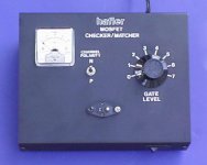
Here is what I use to grade MOSFETs. If used in pairs or triplets they all have to match ±10% on Vgs. If you or anyone else wants a matched pair of 2SK134 or 2SJ49 MOSFETs I have them available at $25/pair +postage to USA
Also, the PCBs he is selling have no guarantee that they are actually intact and working. If you read his statement carefully you will see he offers no guarantee. FWIW, I purchased 3 XL-280 PCB "pulls" from Hillig at Musical Concepts and all 3 were bad.
The numbers written with magic markers on the MOSFETs he is selling are not the bona fide Hafler grade numbers. Hafler stencils their numbers on MOSFETs and does not put them on with a magic marker. Also, the Hafler grade numbers are 1-7. I have never, ever, seen the number "0" (zero) on a MOSFET. I have, however, seen some bad 2SJ49 MOSFETs that were "leaky" and no longer usable and when tested came up with a grade number of zero.
Here is what I use to grade MOSFETs. If used in pairs or triplets they all have to match ±10% on Vgs. If you or anyone else wants a matched pair of 2SK134 or 2SJ49 MOSFETs I have them available at $25/pair +postage to USA
Also, the PCBs he is selling have no guarantee that they are actually intact and working. If you read his statement carefully you will see he offers no guarantee. FWIW, I purchased 3 XL-280 PCB "pulls" from Hillig at Musical Concepts and all 3 were bad.
Attachments
- Home
- Amplifiers
- Solid State
- Hafler DH-200/220 Mods