It depends on where the diode is used. To rectify 50 or 60 Hz AC for power - none at all. It may even create more supply noise, I don't know. It will conduct more current during cut-off, how much is the question.
They actually designed the 1N400x and 1N540x series for low frequency AC (from normal mains) rectification use. Same for rectifier bridge assemblies. So to decide an engineer whose job it is to design these things is wrong based on listening tests seems completely unreal to me. Engineers who design semiconductors don't come off the street. They attend University and only the brightest ones get hired to do this stuff. They even have a real lab with very advanced test equipment. Everything they do is proved in industrial applications where reliability is critical. Same for the quality of a power supply (noise and regulation for example).
I only mention this because the folks I see recommending stuff like this are self appointed experts without formal training in this area. You have to be really careful what you read on the internet! I get my information from talking to these people, and data sheets and application notes (not "white papers" !!!!). In fact, the best information you can hope for is peer reviewed application notes from the engineering departments of large semiconductor manufacturers. Motorola and On Semi (same company really) put out some really top notch app notes, as have some other companies. Stuff from the 50's, 60's and up are really great reading and still valid except in the case where new processes and technology / materials have allowed a change. But always read carefully what the test conditions are and do they even relate to what you are actually doing. They even have an app note on mounting transistors and other semiconductors. That should be required reading for every hobbyist and especially technicians!
There are some excellent articles on power supply design from the 50's on up by these companies. This is all valid and proved in the field and lab. Read the entire app note so you get all the rationale and reasons for doing things. This education is better than what you get in university. It is peer reviewed and written by working engineers.
-Chris

Chris, I guess the other part won't even read your overly valid statement, and if he did, he'd still believe in his alternative facts. I appreciate your patience anyway.
Best regards!
Best regards!
Excuse me?? First up Kay Pirinha, I read everything written in my direction, even considering half my questions remain unanswered..Chris, I guess the other part won't even read your overly valid statement, and if he did, he'd still believe in his alternative facts. I appreciate your patience anyway.
Secondly, what alternative facts? Please state these alternate facts I have espoused....
The fact is I ask simple questions, for example the diode question, no alternate facts, just a question, not hard to comprehend.
Maybe the capacitor thing got you going? I could have used any number of exotic caps in the drain to ground connection but I didnt, I used a mass produced quality polypropylene cap that cost 2 bucks, and jeez, Chris said the best caps are polyester/polypropylene....
As for "Chris told you to leave it alone" Get off your high horse, I had a transistor go bad, maybe it was the best thing to happen while the amp was on the bench rather than in service connected to speakers.
You dont know anything about my background but I choose not to judge others regardless how expert/experienced they are or are not in any given field.
no need to be sorry Chris, as I've said in previous posts I appreciate the time you have spent answering.
Q13, in the DH220 circuit it has a 120pf cap across it, the DH200 does not, is this worth adding in?
I ask questions when I can't see an obvious previous answer in the thread, it may have been asked but after 120+ pages things get lost and I know there are many more ppl reading than posting and hoping to find answers to the same questions.
Thank you.
lol! Of course. It is difficult to find specifics in a long thread.
Okay, Q13 has C17 from collector to base. I show it as 150 pF in my information (close enough). C10 is emitter to base at 330pF. These are normally for HF stability, and they also swamp out capacitance variations in the transistor with voltage swing. Normally I would do a sweep (Bode plot) to see if there are any peaks in the response to see if you need to do that. I suspect that with the new transistors they discovered they had to add that capacitor and maybe adjust other part values to maintain stability. Back then changing part manufacturers often meant you had to adjust HF stability parts. Outputs were common things to watch for for that. Even today this can be an issue.
So ... what to tell you? If they are the original transistors I might not, but I would measure it to be sure. If you put new transistors in, look at the other local part values (resistors, etc ...) between the DH-200 and DH-220 and maybe make the unit look more like the DH-220. In other words, replace components and install those capacitors.
I do not want to give you bad advice and this really needs some tests to be done. Any frequency issues will probably be above 100 KHz on up to past 1 MHz. Not normally a problem above rolloff, but the individual parts will operate above 1 MHz. Best to make certain everything is happy. One thing for certain, if they were not needed in the DH-220, they would not be there. Without a engineering change order (ECO) or modification bulletin I would tend to leave things as they are. But back then it doesn't mean everything was okay and maybe they should have issued a modification for the DH-200.
A Bode plot is generated with a swept oscillator synced to an oscilloscope horizontal (some new ones have this function - mine does) and a detector connected to the vertical input. You could just use the output raw without a detector, but you would be looking at the envelope and would lose resolution. It is basically a frequency response plot, but way beyond the audio passband. So a sound card with a 192 KHz sampling frequency will not do this to a high enough frequency (96 KHz).
-Chris
yes you're correct 150pf, I have printed the 220 circuit in A3 to match my 200 circuit diagram, easy to compare this way.
all the transistors are the same, same spots, same resistors and caps around them, just the 150pf was added across the 2N5415.
120pf came from comments way back in the thread, shows you should always double check the parts list! 😉 a typo from the poster I guess. I have 150pf in styrene so I'm covered if I add it.
I have a 2 chan scope and it has inbuilt signal generator, it's not a hi end device but I'm slowly learning more and more about it when time permits!
I notice the 220 has 0.01uf film across the 100uf 80v caps, so there are a few things added to the 220 that I have done without noticing them on the 220 schematic (haven't studied the 220 schematic much but will do so now).
Hi Sonic Art,
Ignore the 0.1 uF caps across the main filters as they don't do much. HF bypass should be at the point of load (the amplifier PCB) and I think it has bypass caps in place already. I'd have to look. The idea is to get rid of HF content after rectification, the value should be higher and a film cap to do that effectively. 1 uF at least.
Learn your scope! Perfect! Often an analogue scope is better than the new digital scopes. So picking up a cheap 100 MHz dual trace is a good idea, they should be cheap. To give you an idea, I have a Philips PM3070 that is better at CD eye patterns than my Keysight MSOX3104T. The Keysight is the first digital scope that is sort of useful for looking at eye patterns - or I would never have bought it. I have an Agilent 54642D that hints at being useful for CD eye patterns, that forced two scopes on the bench.
Be aware that digital scopes can lie to you. They may display a waveform that is incorrect if the settings are wrong. You also need 4~5 x the bandwidth minimum to display a waveform that approximates the real one unless it's a sine, and I wouldn't trust that either!
I guess you could try putting the 150pF cap in. Use your scope and watch for oscillation with the cap installed. Polystyrene is perfect! I use 630 V units generally speaking. I would measure distortion before and after.
-Chris
the bypass caps I was referring to are on the pcb's across the 100uf caps, not the main filter caps directly after the bridge. I have not put any caps across my main caps (18,000uf kemet ones).
DH200 has no bypass across the pcb caps, DH220 does. I believe it has one across the bipolar cap too.
your thoughts on bypass across the main supply caps? you say 1uf or greater? I have plenty of solen mkp on hand in all sizes 1uf upwards. I see talk in this thread of guys using 4700uf and 470uf across the main caps then a film across as well.
Those bypass caps may be of some value, an incremental improvement compared to getting the circuit running right. Matching diff pairs and some other parts make more of a difference. One thing though, they will not hurt at all.
Don't increase main capacitance. That causes problems. You can use film caps maybe up to 10 uF, I would stick around 1 ~ 4u7 at sizes that do not stick out - they have to fit neatly. All you're doing is reducing HF impedance and you can use polyester types as they do not see a signal voltage across them. So just use common sense, use a value that isn't too large with a little extra voltage rating.
When you read in threads, you will have information from every kind of person of varying skill levels, and understanding of electronics. Most times if they can only offer listening experience, the information is not valuable. In fact, most information based solely on listening tests is just repeated hear-say and may be opposite to what is actually true.
Yes, but... TI refuses to correct errors in their data-sheets. (See the thread on their JFE150 JFET here on DIYAUDIO).In fact, the best information you can hope for is peer reviewed application notes from the engineering departments of large semiconductor manufacturers. Motorola and On Semi (same company really) put out some really top notch app notes, as have some other companies.
Intersil and Analog Devices (including Linear Tech) have great application notes...Keysight has kept alive a lot of the legacy info from Hewlett Packard from whose loins it was sprung fully clothed.
Hi Jack,
True, however that is miles better than pure speculation and the "whatever sounds good" that is often posted. I would rather read app notes all day long than a "White Paper", and those are a lot better than "White Papers" from audio companies!
The very best education you can get is technical papers from Engineers and scientists in their fields where their material has been properly vetted by their real industry peers. That is in every single field of study, not just audio or electronics.
ANy company that makes an effort to preserve information should be congratulated - especially service information. The "Wayback Machine" is a wonderful resource, and I do support them with donations. I think many of you out there should consider donating to that more than worthy cause.
thanks Chris, I understand where you are coming from hence I ask questions rather than just implement anything someone might suggest on a forum.
one thing, you say larger main caps can cause problems, I would suggest you elaborate on that as again, there are lots of ppl reading this and a clear explanation will be of more help than just "causes problems" no offence 🙂
one thing, you say larger main caps can cause problems, I would suggest you elaborate on that as again, there are lots of ppl reading this and a clear explanation will be of more help than just "causes problems" no offence 🙂
No problem,
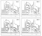
As the capacitor becomes larger, they hold the charge higher. A rectifier only conducts when the supply in the cap is lower than the voltage from the transformer (minus diode voltage drop). So therefore all the energy you are using in the amplifier must be transferred over a shorter period of time (conduction angle). That then means the current pulse (read spike) must be much higher to transfer the same amount of energy. So, IR losses will be higher everywhere (including the transformer). Because the time period is even shorter, we have higher frequency noise content with a much higher amplitude. = more noise on the supply.
For regulators and output stages, 120 Hz (100 Hz) is a lot easier to get rid of then all their harmonics are. So why create more high frequency content than you need to??
None of these things are positives. Not only that, but the only time it would actually matter is when you are peaking (clipping if you are that high) and the difference in power output is TINY! What we have here are folks who focussed on one idea without considering the drawbacks - or even the practical difference it makes. So why do some companies use massive capacitance? Marketing.
So, if you can, figure out what is actually happening and use some common sense when coming to a decision. I know most are just learning, but this is a great illustration of how an idea may sound great, but really doesn't hold any water. Properly engineered products don't skip on capacitor size to be cheap. (that's what companies who advertise the size of their capacitors would have ou believe) They do design in the proper size in fact.
Hi everybody:
Anyone of you could let me know how to wire a Hafler DH-200 to run at 220 voltage?
I recently purchased a unit on eBay.de, it seems someone try to mod it, but, apparently, abandoned the job in the middle.
I'm afraid to power up this old beast and kill it.
Attach files
https://www.diyaudio.com/community/...]=31131&hash=47fe570082a68b58630077fa54345d4f
The main fuse is already burned before I grab the amp.
Any help will be much appreciated,
Antonio
Attachments
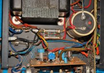
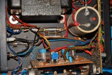
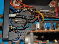
Hi: The pictures are taken by me from the amp I grabbed.
I saw the burned main fuse are rated 2,5A/125V!!!!
Maybe the person who tried to rewire it for EU voltages forgot to change the fuse accordingly...
I saw the burned main fuse are rated 2,5A/125V!!!!
Maybe the person who tried to rewire it for EU voltages forgot to change the fuse accordingly...
2.5 A and 125 V calculate to a maximum power consuption of just 312.5 VA. The fuse appears to be not up to task, as I expect some higher power consumption, especially if the amp plays loud.
Best regards!
Best regards!
- Home
- Amplifiers
- Solid State
- Hafler DH-200/220 Mods