Does anyone know how to get vinyl transfer letters made for an amp logo? See attached mockup done on my computer. (Not perfect, but close enough for my needs) My case needs repainting and I would like to get a fresh new look for the logo as well. If I can find an affordable source, I'd be willing to get a larger quantity and make them available to other members who want to do the same.
Q2. - my fins are a bit faded and scratched, any recommendations to refresh the black anodized finish? I've read that painting aluminum is difficult and reduces the heat dissipation properties of the anodized metal.
Thanks! - Sixto.

Q2. - my fins are a bit faded and scratched, any recommendations to refresh the black anodized finish? I've read that painting aluminum is difficult and reduces the heat dissipation properties of the anodized metal.
Thanks! - Sixto.
Hi
I do not know of a source for transfer lettering but if an emblem would work I have seen whole front/back panels being done using the pcb fab. Member “bonsai” has done it on his phono xltra preamp. Black solder mask, gold plated holes/pads and white silkscreen for the graphics.
You would specify your pcb thickness which can be very thin. They do edge plating too so that would look cool done with gold plating. It is possible to not need any silkscreen if plating is done in gold. There is also aluminum core pcbs to but the solder mask is usually white for led usage have to look into that.
I think they only accept Gerber data for pcb fab so that’s a matter of doing a graphics file conversion or import into pcb software to generate a Gerber file.
At one time we had a local print shop make transfer graphics on adhesive backed transparent plastic.
I hated doing transfer lettering, never could get it straight 🙂
As for fins, you could use a permanent ink felt marker, but it leaves a somewhat noticeable mark. If you do all that’s visible might make it look better.
Last edited:

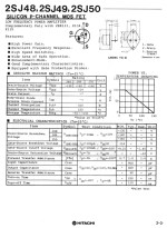
I found a source for some NOS 2SJ48/2SK133. (Or alternatively) 2SJ50/2SK135. My Hafler DH220 has 2SJ49/2SK134.
Assuming I can get either matched pairs, or individual spares that match the VGS of my existing transistors, would using either of these in combination with existing cause issues like added offset or distortion?
The only difference. I can spot on the data sheets is the max drain/source voltage 120v for 48/134, 140v for my 49/134 and 160v for 50/135. Seeing that rail voltage is around 70v, and I’m don’t intentionally push the amps to clipping…Would either of these be a suitable replacement (individually or in pairs) if one of my power transistors goes poof in the future, and is one spec better than the other? Furthermore, would there be any issues from one channel to the other if the replacement transistors were used on only one channel?
P.S, I’m aware of the Exicon option, but they are different enough, that I don’t think they would work as individual replacements…
Thanks! Sixto.
Attachments
"Does anyone know how to get vinyl transfer letters made for an amp logo?"
This unit and software seems plausible for anything you may want...
https://www.amazon.com/Cricut-Explo...l+printer+machine&qid=1699227286&sr=8-11&th=1
HTH,
David
This unit and software seems plausible for anything you may want...
Cricut Explore 3 - 2X Faster DIY Cutting Machine for all Crafts, Matless Cutting with Smart Materials, Cuts 100+ Materials, Bluetooth Connectivity, Compatible with iOS, Android, Windows & Mac, Mint $289
Possible vendor:https://www.amazon.com/Cricut-Explo...l+printer+machine&qid=1699227286&sr=8-11&th=1
HTH,
David
Thank you David, the price seems right, I just need to dig deeper into the specs to make sure it can do the small letters I’m looking for… I found a few shops online, but they all said my font size was too small for their machines. They required 2mm line thickness min, and I’m looking for 1mm.
Sixto.
Sixto.
Too bad that machine will not work...
On reflection, I remembered this logo :

and it is still available
https://www.ebay.com/itm/3726329126...QNeQkEW5Pn2A3N+KID63H3q/sC|tkp:Bk9SR8jwzbf0Yg
HTH,
David
On reflection, I remembered this logo :
NOS HAFLER "Hafler Amplifier" Front Panel Self-Adhesive Logo Strip: ($13.95/ea)
and it is still available
https://www.ebay.com/itm/3726329126...QNeQkEW5Pn2A3N+KID63H3q/sC|tkp:Bk9SR8jwzbf0Yg
HTH,
David
Be very careful buying EOL parts on the internet
Read Bob's write up on matching mosfets. Matching insures current sharing for paralleled devices. DH-200/220 does not use a ballast resistor.
https://www.cordellaudio.com/poweramp/DH-220C_MOSFET.shtml
You want as a minimum a mosfet Vds or bjt Vce breakdown V of no less than 2xVpk or your total rail +/-70 = 140V
Do not mix up devices, use same devices in parallel and their complements
Exicon are fine replacements, although the TO-3 is EOL
Thanks Rick, that pretty much rules out the 2SJ48/2SK133 (too low of a breakdown voltage) or using the higher voltage 2SJ50/2SK135 unless I can source matched pairs. I’ll keep looking for spares that have the right specs.
Sixto.
Sixto.
Hello all. Brand new here. I haven't messed around with component level electronics repair in a loooooong time. Reading through these pages is a serious refresher course. I'm amazed at how much I remember but even more amazed at what I have forgotten. Sad.
I got ahold of a working DH-200 35 yrs ago and stashed it away until last week. No output. Went through some checks, cleaned things up, reseated/greased the mosfets and it's working now.......yay! Checked the OPS bias (235 ma/270ma) and DC offset (15mv/23mv).
I do plan on upgrading but for now have a problem with the 10000 uf PS filter cans? It sometimes sounds like it putting a half second of 120 hz on the outputs on cold power up. It plays ok after that. I can't find a source for the original cans. I had Electronics training in the military 42 yrs ago but haven't used that training since then. I simply don't know what uf to get. Dont want to over current the bridge or burn up an already marginal designed archy-sparky power switch. Anyone know of where to find suitable replacements? Maybe send me a link?
Thanks,
Lonnie
Seems more like a bad solder joint than the supply capacitors, or else a loose screw terminal, or input cables.
Yes, the 1/2 second humming/buzzing on power up is on both outputs. Sounds like 120 hz from my days of running live sound for bands.
I've checked the PS connections, everything is tight and shiny solder. Touched up the P-6 wiring input and output connections as well as others that were questionable. Really though, it was soldered by someone who knew what they were doing. I don't think anything that I did was an improvement.
There IS a missing component however, the .005 uf C14 cap for the neon over temp circuit. Appears to me C14 is to bypass the neon light during normal operation then if one of the temp switches opens the power is sent through the over temp neon light. There is a resistor shown for neon light on the schematic however it has no nomenclature nor shown on the parts list. I have to assume the neon resistor is part of the neon light assembly?
Anyway, the way it's wired, without the C14 bypass cap, I would assume the neon light would have been lit continuously, and burned out long ago. I don't feel the C14 cap has anything to do with the buzzing noise on power up BUT like I said, it's been many years since I've performed any component level trouble shooting.
Will old dry filter caps buzz on power up until they charge up? Will they get better or worse over continued use?
Sorry about the dumb questions fellas, I know this isn't a trouble shooting thread. I just want to get a good kit before starting mods.
Lonnie
Last edited:
Then if the screws on the capacitors are tight, there is some other problem to track down.
But clearly it is in the power supply area. I suppose the two main capacitors should be checked,
if not by measurement, then by substitution.
Or you could burn it in for a few hours, and then see if the problem has changed.
Although I've built a few of these, I never had a problem. Wouldn't worry about the lamp and small cap though.
Thanks, rayma.
The 1/2 second buzzing issue on power up has disappeared. Not exactly sure what fixed it. Recap is next.
Anyone have recommendations for cap upgrades?
The 1/2 second buzzing issue on power up has disappeared. Not exactly sure what fixed it. Recap is next.
Anyone have recommendations for cap upgrades?
Update, figured out what was causing the buzz on power up, the Monster Power "Green" surge protector. Apparently the inrush current from both the Onkyo 818 and Haffler DH-200 freaked out the active components in that surge protector. Not a peep during power up since I moved the Hafler to the wall socket.
I'm putting together a BOM for ecaps, pp caps and semis for a restoration of this DH-200. Hopefully someone can confirm my choices and keep me from making bad choices.
Thanks,
Lonnie
I'm putting together a BOM for ecaps, pp caps and semis for a restoration of this DH-200. Hopefully someone can confirm my choices and keep me from making bad choices.
Thanks,
Lonnie
just tossing this out there...
you might want to consider Richard Marsh's cascode add-on. supposedly good results for little cost.
you might want to consider Richard Marsh's cascode add-on. supposedly good results for little cost.
I'm putting together a BOM for ecaps, pp caps and semis for a restoration of this DH-200.
Large screw terminals caps are more difficult to source.
But they should be low ESR, high ripple current, and mechanically fit the mounting.
Voltage rating should be 20% (or more) higher than the working voltage at nominal AC line.
Hello all. I've decided to upgrade my DH-200. I bought the Fantasia ultimate audiophile upgrade kit and I'm stuffing boards at the moment.
Has anyone used the speaker protection board in the link below? Should I be concerned that it ties the speaker grounds together?
Thanks,
Lonnie
https://www.ebay.com/itm/2948295361...uJFfs9b2DHHu4K6njP3zkZ09Ln|tkp:Bk9SR6616fCvZA
Has anyone used the speaker protection board in the link below? Should I be concerned that it ties the speaker grounds together?
Thanks,
Lonnie
https://www.ebay.com/itm/2948295361...uJFfs9b2DHHu4K6njP3zkZ09Ln|tkp:Bk9SR6616fCvZA
- Home
- Amplifiers
- Solid State
- Hafler DH-200/220 Mods