Dear Mr. Slavic,shouldnt R16 R31 be removed ? it will form RC filter with headphone impedance -and you cant compensate for cable capacitance this way.
i also used line filter as no filtering device after 7824 ,next time use a low noise transistor please +1 irf610 wont be much of an expense
R16 and R31 are used to remove parasitic charges which appears at powering on the circuit. Their values are enough high, to not disturb this circuit functionality. Please remark, this circuit runs with single supply, and before output capacitor the voltage are half of supply voltage. With delay circuit that cannot be eliminated.
Remark regarding IRF610 - is an often used transistor in audio electronics regarding its low gate capacitance. Same famous circuits: Mr. Pass preamplifier (Bride of Zen) or amplifiers, or Ernő Borbély All FETs circuits, or long time ago was publised by SDS Lab one class A headphone amplifier - but I am shure on the net you can find hundred of other famous circuits using this mosfet.
You have right. I built several headamps, and is enough 2x amplification.The gain of 11 seems to be inssane, I would prefer a gain og 1 or 2 is that possible.
Here, in this circuit the ration of R13/R17 determine this. Try to decrease R13 to 1.2-2.2kohms (right value will depend by your source).
Hi
i know there should be a 50-100pf cap for Q7,Q12
-can someone help calculate the snubber resistor and capacitor for this irf610
http://www.ti.com/lit/an/slpa010/slpa010.pdf page 12
http://thesciencedude.com/projects/...Pad (ALP)/LIBRARY/snubber_circuit_design.html
i know there should be a 50-100pf cap for Q7,Q12
-can someone help calculate the snubber resistor and capacitor for this irf610
http://www.ti.com/lit/an/slpa010/slpa010.pdf page 12
http://thesciencedude.com/projects/...Pad (ALP)/LIBRARY/snubber_circuit_design.html
Last edited:
Dear XSlavic, was necessary to insert those 22pF? You have high frequency oscilations? Why is better now the sound?
Till now I made several headamps. The best sounding one is a Heed Canamp clone: /keret.cgi?/headamp/HeedCanamp.html :::::: Powered by: www.webtar.hu ::::::*
Sound is warm, detailed, very pleasant.
From instrumentation point of view, means not as listening, just as technical parameters, is this one:
/keret.cgi?/headamp/TPA6120A2.html :::::: Powered by: www.webtar.hu ::::::*
The sound is very clear, but cold.
Yes,it did the job .Now the sound is perceived like a straight line more or less not an arc as without it with lows and highs at its ends.Did not try zobel for mosfets yet.
I have something similar to heed Canamp,a diamond buffer with bc560 and bd139 -some pcbs but not tested yet,thinking of a parallel tpa6120a2 -have the ics and just for fun
-this amp is very nice,better than the Alc1150 with opa1642 i was listening to before ,sounds well even with pcm5102 -good details and you can hear the circuitry of the DAC
Last edited:
found the original design,do we need that 5.6pf for the mosfet ?
http://www.acoustica.org.uk/t/naim/preamp_pics/Gain_board_schem.jpg
http://www.acoustica.org.uk/t/naim/preamp_pics/Gain_board_schem.jpg
No. Mosfets input capacitance are much higher.
R12 and R27 should be mounted as close as possible to gates, to prevent oscillations.
R12 and R27 should be mounted as close as possible to gates, to prevent oscillations.
Hello. This is my first post here.
I put one of those together. While the sound is not bad in original form (no upgrades yet), the gain is absolutely ridiculous. At about 2.5 on a scale from 1-10 it is very loud! Someone mentioned here something about changing R13 (?) in order to reduce gain. Is there any schematic available. Thanks in advance.
I put one of those together. While the sound is not bad in original form (no upgrades yet), the gain is absolutely ridiculous. At about 2.5 on a scale from 1-10 it is very loud! Someone mentioned here something about changing R13 (?) in order to reduce gain. Is there any schematic available. Thanks in advance.
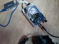
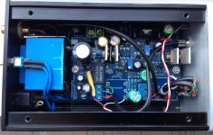
Hi!I modified the PCB again.
Convenient installation.
Using relatively simple LM7824 as a voltage regulator IC. Its experience in practical use. Has a good power supply ripple control.
I bought the set on the aliexpress.com, but the seller did not provide me a circuit!
Please help in the provision of schemes.
Dear all!
Here we discuss
HA-PRO Single-ended MOSFET
CLASS A Headphone Amplifir.
Let us systematize our knowledge, experiments to improve the sound of the amplifier, and modding, as a replacement of a particular denomination coca is part affect the sound?
Here we discuss
HA-PRO Single-ended MOSFET
CLASS A Headphone Amplifir.
Let us systematize our knowledge, experiments to improve the sound of the amplifier, and modding, as a replacement of a particular denomination coca is part affect the sound?
65mA or 650mV across 10 ohm resistor. You can bias it deeper at 100-200mA and larger heatsinks are required
65mA or 650mV across 10 ohm resistor. You can bias it deeper at 100-200mA and larger heatsinks are required
HI !
resistance of 64 ohms my headphones
Designer I bought supplied 22-ohm resistor is written 600 mV / 22 Ohm = 27 mA.
but on medium began prisuvstvovat distortion, I raised the quiescent current to 50 mA distortions became smaller, but the output transistors become much bask in design offers the radiators are not provided.
And so I ask - is there a dependence of the resistance and quiescent current of headphones? How do I choose the optimal mode quiescent current ..... listening?
What is the quiescent current to typically IRF610 -?
- Home
- Amplifiers
- Headphone Systems
- HA-PRO Single-ended MOSFET