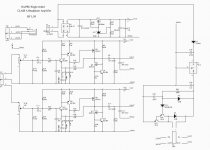
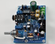
CLASS A Headphone Amplifier
Some material, convenient friends of the production.
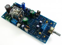
Need to pay attention to, it USES AC 24-0 input, low voltage will make failure noise voltage.
Had better not exceed AC28-0.
10 the resistance controls the MOSFET IQ,
About 650 MV / 10 R = 65 MA
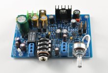
It is a, very hot. Headphone amplifiers
Some material, convenient friends of the production.
Need to pay attention to, it USES AC 24-0 input, low voltage will make failure noise voltage.
Had better not exceed AC28-0.
10 the resistance controls the MOSFET IQ,
About 650 MV / 10 R = 65 MA
It is a, very hot. Headphone amplifiers
Attachments
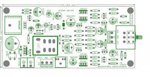
as sold in kit form on ebay for $30+$10 shipping
The mods should probably delete or move this thread, as it is not a diy project.
It is cheap though, I'll give you that.
The mods should probably delete or move this thread, as it is not a diy project.
It is cheap though, I'll give you that.
This looks very similar to one of my designs on the thread: Simplistic Class A MOSFET Headphone w Feedback: have I got my values right?
This new PCB looks much better, than previous one. What about soud? What is your impression? Who else try it? A/B tests or other comparison as reference?
The transformer should be 20W, and the dissipation/chanels mosfets (Q3&Q6, respectively Q8&Q11) is approx 3W/chanel.What transformer VA rating should I use for this kit?
How largr the Heatsink? Thanks.
The transformer should be 20W, and the dissipation/chanels mosfets (Q3&Q6, respectively Q8&Q11) is approx 3W/chanel.
AC24V voltage is more important
OR AC12-0-12 Series connection
It really isn't a good idea to use 16V rated caps at the output. If the top mosfet fails open... Good practice for output caps is to use at least a voltage rating equal to the unregulated rail.
shouldnt R16 R31 be removed ? it will form RC filter with headphone impedance -and you cant compensate for cable capacitance this way.
i also used line filter as no filtering device after 7824 ,next time use a low noise transistor please +1 irf610 wont be much of an expense
i also used line filter as no filtering device after 7824 ,next time use a low noise transistor please +1 irf610 wont be much of an expense
Fifty bucks including a case on fleabay. If I can find a cheap enough xformer I might just give it a go..
- Home
- Amplifiers
- Headphone Systems
- HA-PRO Single-ended MOSFET