Ditto!
Might take some minutes more in order to make me sound (somewhat) worthy, that said if ZMenglish works I should do fine... no offense ZM 😀
Edit: Email out! (not sure of the "worthy" thing though.....)
Might take some minutes more in order to make me sound (somewhat) worthy, that said if ZMenglish works I should do fine... no offense ZM 😀
Edit: Email out! (not sure of the "worthy" thing though.....)
Last edited:
Hello, Coolnose,
If you become the distributor of the H2 on Europe, I will be very happy to receive an H2.
Best regards
If you become the distributor of the H2 on Europe, I will be very happy to receive an H2.
Best regards
I have contacted Pa as requested, hopefully I am worthy 😛 . That said I will start a dedicated thread for the handout so no need to let me know here as it will be hard to keep trace of everyone...
Hi,
Nelson, thanks a lot for the offered possibility, but ZM nailed it better than I could. I moved to France recently (two months ago) and still have a temporary residence permit, looking toward making it permanent, but it will take some time, and still at this moment I am not sure what the outcome would be.
So, as it is, we left practically everything in my ooked country and moved here.
That means that my audio gear is reduced to a pair of heafphones and a DAC that fit in my pocket. So, in an sense, reset. Start from zero.
That means that I have no single amp nor speaker yet. Tools neither.
But, I am keeping a positive attitude. I have eyed some nice second-hand Cabasses in the area, but they will have to wait, because my wife put the TV higher in the priority list than speakers (no TV yet either).
Regarding re-starting diyaudio hobby, there's a ray of light and a glimpse of hope: I found a group of electronic diyers and they allowed to me have access to their workshop/tools, so I may start to build "my first amp here" soon.
Sorry for off-topic, as this content belongs to the Pass pub and not here, but I felt obliged to explain the current situation.
Kind regards,
P.s. Can't wait to see the Buring amp event, makes me feel like almost there 😉
A quick follow up on the kind offer of NP for H2 kits:
gary s has opended dedicated thread for those "down under" here:
Pass H2 kits for Australia and New Zealand.
and I did as well for the members on the old continent here:
H2 (Harmonic Generator) Kits for Europe
Cheers,
Max
gary s has opended dedicated thread for those "down under" here:
Pass H2 kits for Australia and New Zealand.
and I did as well for the members on the old continent here:
H2 (Harmonic Generator) Kits for Europe
Cheers,
Max
I wonder the subjective effect of having different phase H2, multi way design. Since we use to have multi ways speakers, and play with their phase to crossover them, do this have a significant subjective effect on depth ...? (Moreover when actively multi amped with tube or high H2 amp...). Doesn't it gives a weird effect ?
I wonder the subjective effect of having different phase H2, multi way design. Since we use to have multi ways speakers, and play with their phase to crossover them, do this have a significant subjective effect on depth ...? (Moreover when actively multi amped with tube or high H2 amp...). Doesn't it gives a weird effect ?
If you are multiamping then it will. Lets say you have a preamp with neg H2, a poweramp for mids/high with neg H2 but the bass amp has pos H2. For example, you listen to a trio with violin, viola and cello, your brain perceives the cello more forward then it should be. Adjust the bass power amp to now get neg H2 and the cello moves back into place. It depends on your amps and how much H2 is present. Also as Mr. Pass has pointed out the effect is most noticeable under 4k.
Hope this helps.
nash
This should be something really interesting to play with, thanks a lot 🙂If you are multiamping then it will. Lets say you have a preamp with neg H2, a poweramp for mids/high with neg H2 but the bass amp has pos H2. For example, you listen to a trio with violin, viola and cello, your brain perceives the cello more forward then it should be. Adjust the bass power amp to now get neg H2 and the cello moves back into place. It depends on your amps and how much H2 is present. Also as Mr. Pass has pointed out the effect is most noticeable under 4k.
Hope this helps.
nash
Thank you Nelson for your generosity, I just received my H2 kit in the mail, great birthday present for me (11/11).
Hello hifibluedevil. My thanks to Mr. Pass for his generosity, and for sending me two kits of H2 Preamp V1.
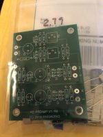
I have assembled one kit; easy but ran into this particular trouble. I did not check the pinout of the enclosed FETs [Q1 and Q2] before soldering in place.
The PCB shows two possible positions for a FET. The one close to the 1000uF capacitor [position 1] has a a bottom-view pinout which is [D G S]. The one below it [position 2] has a botton-view pinout which is [D S G]. The two positions are not the same. I made the mistake of soldering the supplied FETs [D S G] in position 1 which is[ D G S]. Didn't work for both channels and no damage was done to the FETs. Drain current was ~ 1 mA
I desoldered one FET [D S G]; like a dentist pulling a wisdom tooth. I put it in its proper position 2. This channel works.
I lost the other FET; Its leads were delicate and I was rough. So I borrowed one FET from the second kit and put it in position 2 where it belongs. Both kits showed awritten Pinch-Off voltage equal to 2.79 V. for the 4 FETs. I was safe!
I'll show a picture of my build tomorrow.
Best
Anton
I lost the other FET; Its leads were delicate and I was rough. So I borrowed one FET from the second kit and put it in position 2 where it belongs. Both kits showed awritten Pinch-Off voltage equal to 2.79 V. for the 4 FETs. I was safe!
I will send you another pair.
🙂
I will send you another pair.
🙂
Thank you Mr. Pass for your generosity and help.
Picture of build
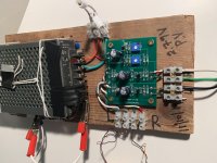
The picture shows my build of H2 PREAMP V1 R0. Its assembly was easy and straightforward. I could use more practice soldering/desoldering. Pay attention to the bottom-pinout of the enclosed FETs [Q1 and Q2] . It must match the required insertion points on the PCB. Please see my earlier post.
The 24 Vdc PSU is an oldie. The shunt of the aligator clips connects its body/case to power ground/earth. Its voltage output is {transformer} isolated from the higher voltage front end.
Its voltage output is fused with an X-mas light bulb; which is expected to blow at ~200 mA. The bulb lights up briefly on turn on.
I drove the input of H2 V1 with the headphone output of my laptop. I listened to the output of H2 V1 using my Grado headphones [32 Ohms]. It work very well; but I needed to raise the volume on the laptop output to get an adequate sound pressure. Understandable; because H2 V1 has a high a output impedance, and works as a current source amp to the lower load impedance Grados.
The build did not achieve the suggested Pinchoff voltage [PV] of 2.79 V. The Left channel FET had a minimum PV =3.10 V at a drain current ~30 mA . It was calculated from the voltage drop [9.83 V] across the FET's load resistor [332 Ohms]. The minimum PV for the Right channel FET was 3.38V, at its drain current of ~29 mA.
In order to attain the required PV of 2.79 V, it is possible [for me] to increase the value of the resistors in the schematic [R14 and R17; each equals 33 Ohms]. Or the output voltage of each regulator needs to be decreased.
I'll collect more data on the build as is and report.
Best
Anton
Attachments
Hi Papa,
Is there a way to get the kit in the US? I have an M2 and am curious to see how much more 2nd Harmonic the system can take before it gets overwhelming.
I was close by (SoCal) but unable to make it to BAF this year. Enjoyed it vicariously through the updates and photos, looks like a wonderful time was had by all!
Best,
F
Last edited:
The FETs [Q1 and Q2] in the H2 V1 kit are very valuable; like it because PASSWORKS has already done work to match them up from a large collection of FETs for this application.
The attached photo shows a possible approach by the DIYer to safeguard the FETs, and to do its own FET testing matching under dynamic conditions.
I cut an 8-pin DIP OpAmp socket into two subsockects. I filed off the excess plastic. This socket is to be soldered to the PCB and the FET [J112] is then inserted for testing or left in permanently.
I hope this trick may save heartburn in assemling the kit.
Best
Anton
Attachments

Hi Mr Pass,
how do we get those boards here in good ol' Europe?
(or will you give the Gerber data?)
all the best for BAF
how do we get those boards here in good ol' Europe?
(or will you give the Gerber data?)
all the best for BAF
See here, perhaps.Hi Mr Pass,
how do we get those boards here in good ol' Europe?
(or will you give the Gerber data?)
all the best for BAF
Free H2 (Harmonic Generator) Kits for Europe
The build did not achieve the suggested Pinchoff voltage [PV] of 2.79 V. The Left channel FET had a minimum PV =3.10 V at a drain current ~30 mA . It was calculated from the voltage drop [9.83 V] across the FET's load resistor [332 Ohms]. The minimum PV for the Right channel FET was 3.38V, at its drain current of ~29 mA.
Perhaps there is some confusion. The Vp on the J112's is achieved by
placing +12 on the Drain, grounding the Gate and using 1 megohm
series resistance from Source to Ground. The Vp is the resulting voltage on the Source pin. The Drain current is a couple microamps.
This is used to decide what the rail V+ voltage should be on the supply
voltage at the test points as referenced by the curves in the article.