
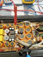
i have checked some pictures on google. So it is a 1.4k HCX in a heatsink of a GZPA 1.4000DXII... Would be interssting, if the mosfets are original, or if i upgrade to 24n40..
Maybe you have some advice?
Maybe you have some advice?
Okay....HCX - it's the Hi Current board in the heatsink of the older GZPA 1.4000DXII.
What are the rail voltages in your amp ? b+ 14.4v of input ?
FDA59N25 - are only 250v but 59A so if yours is the hi-current model, this makes sense.
In all of the 1.4000dxii I've repaired the ones which are being used are FDA38N30 - 300v - 38A.
FDA24n40 - are only 23A but 400v - which are going to be a downgrade, not an upgrade.
However I've never seen amp with FDA59N25. Are You sure these are the originals ?
Keep in mind this are ratings ~ 25Celsius....and this almost never happens in an amp...more like 75-90 😀
Last edited:
Can't take measurements at the moment, because ps is off. Railcaps are 160v,and iam not sure if are original fets inside. I contacted the manufacturer, maybe they can tell me the right one.
It looked like the rail caps could be open or well out of tolerance and was allowing the high-frequency to pass through to the outputs.
Did you look at the positive rail with the scope?
Did you look at the positive rail with the scope?
I will evaluate it later. Without load connected, everything is fine, i can go into clipping.
With load 1,2Ohm connected, and even small input it is allready disturbed. Also the rail voltage dropped very quick, and the oscilloscope cant recognize the voltage anymore.
That occurs allready with 12,5V DC and 7Amps input.
With load 1,2Ohm connected, and even small input it is allready disturbed. Also the rail voltage dropped very quick, and the oscilloscope cant recognize the voltage anymore.
That occurs allready with 12,5V DC and 7Amps input.
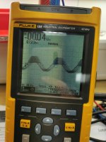
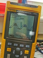
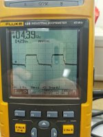
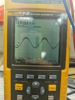
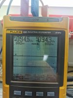
So here are some pictures. Hopefully it will help. 95v with gain at minimum. The other picture with gain at little higher. Input 10 amps.
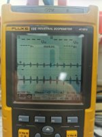
The last picture is pulse from ps fet
Stays stable all the time.
The last picture is pulse from ps fet
Stays stable all the time.
Attachments
Last edited:
I don't know.. If I connect the measure cables on common sec and rail plus, the output is strong distorted, without, it looks like the previous post, last picture. Anyway, if I go on the limit from my power supply, first it breaks down the positive half. Then the amp switch off with protection
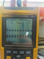
Compare the positive rail to the negative rail. Do they look approximately the same or is the positive rail really noisy in comparison?
Upper one is positive, lower negative. They are nearly the same. I made pictures at different input levels.
I have tested also before the audio input at the driveboard, with driverboard dismounted. The singnal is clean, which is going to the drive board.
I have tested also before the audio input at the driveboard, with driverboard dismounted. The singnal is clean, which is going to the drive board.
Attachments
Last edited:
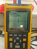
Is the noise on the rails going all of the way to ground? Assuming that the dash/rectangle is ground for the nearest trace.
The low side looks worse than the high side but there is no noise on the negative part of the output signal. That too is odd.
The low side looks worse than the high side but there is no noise on the negative part of the output signal. That too is odd.
On the negative rail, its going completly down to ground. I will try with another power supply, but the other has only 5 amps... Maybe i can reproduce it, so that iam shure it comes from the amp.
I doubt that this is from the primary 12v power supply.
Are you sure that the rail caps are within tolerance?
Are you sure that the rail caps are within tolerance?
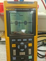
So, it doesn't belong to my supply. What I found, is. If I look at the time base from the ps gate, it starts jumping, from left to right, double and so on. At the same time, when the distortion starts, the ps amplitude starts flickering.
I tested only a few caps, but the values are like new.
Its not a regulated ps. Do you have something in your tutorial about a feedback circuit for this? Also it seems, that there are small spikes, like noise all over the amplitude when it begins to flickering, but realy very small.
I tested only a few caps, but the values are like new.
Its not a regulated ps. Do you have something in your tutorial about a feedback circuit for this? Also it seems, that there are small spikes, like noise all over the amplitude when it begins to flickering, but realy very small.
Last edited:
I have tried something to isolate the problem. I removed one side mosfets from audio, tested without these fets. Problem nearly gone. Installed the mosfets again, and removed the other side. Problem is back. So it comes from the one audio side. I think I I remove drive board and install new drivers.
- Home
- General Interest
- Car Audio
- GZPA 1.4000 DXII