I had it before on another smaller digital amp, that the mute circuit caused this type of problems. Which transistors on this amp are for this circuit?
But then it should be on both audio sides...
But then it should be on both audio sides...
Attachments

Checked all rail caps, also ok.
I believe, that the problem is not comming from the PS. I think there is somehow a big feedback.
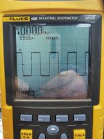
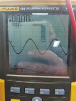
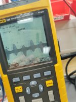
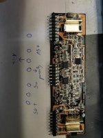
Without the driveboard, i was able to see a good sinewave on the 3rd pin, 2nd row. With board inside, it is not possible to recognize. Looks like bubbels on the osci.
Could it be, that the TL072 is damaged and give a feedback?
I believe, that the problem is not comming from the PS. I think there is somehow a big feedback.
Without the driveboard, i was able to see a good sinewave on the 3rd pin, 2nd row. With board inside, it is not possible to recognize. Looks like bubbels on the osci.
Could it be, that the TL072 is damaged and give a feedback?
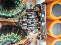
I don't have a diagram for this amp but the muting transistor should be connected to terminals 6 and 16 of the audio driver board.
It's normal to see no signal when the driver board is in the circuit and the amp is producing rail-rail output at the FETs. The noise you see is what the amp isn't able to correct for.
Are you testing with only half of the outputs in the circuit?
Do the FETs driven by the other 21844 have the same problem?
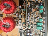
If you're saying that one 21844 and its outputs produce clean audio and the other 21844 and its outputs do not, the problem is likely something that neither shares. That would be the 21844, the MMBTA92 that drives it or something on the main board.
IT's also possible that there is a problem with the B+ supply for the 21844. What is the DC voltage across the capacitor for the high-side supply?
Is the voltage across it clean DC when the amp is distorted?
IT's also possible that there is a problem with the B+ supply for the 21844. What is the DC voltage across the capacitor for the high-side supply?
Is the voltage across it clean DC when the amp is distorted?
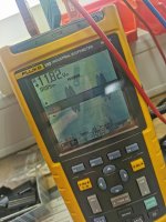
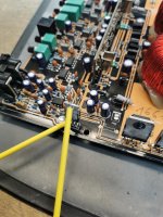
Yes, I had to install two mosfets first..the line is all the time very thick, but if I increase the gain, the bubbles occur. This are the same bubbles, I have on the audio input pin 3 with drive board inside. Also occurs with higher gain.
On the other side is the full bank installed. I measured before there, and there was not this disturbance. Only after I installed the other bank two mosfets. Than it appears there also.
OK. FETs installed for only one 21844 at a time.
Check the capacitor voltage for the 21844 with the FETs installed.
Is one clean while the other is noisy?
Check the capacitor voltage for the 21844 with the FETs installed.
Is one clean while the other is noisy?
Removed the two mosfets from the more noisy bank, and checked the voltage on the other side. Zero gain and gain little higher.
As I have received the amp in the first time, there was the ceramic cap for rca ground blown. Maybe something has to do with it.
As I have received the amp in the first time, there was the ceramic cap for rca ground blown. Maybe something has to do with it.
Attachments
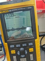
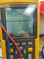
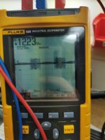
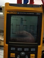
So, if I look at the picture from the 12v regulator, it seems, that the voltage drops to zero and doubles to24v. Is it possible, that that the ground or common center from the rail is somehow interrupted and the rail voltage rise?
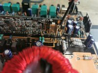
I just read it in the turorial. When the fets are not driven well, the filter inductor acts as a flyback transformer. So it is possible, that the drive board still has some issue.
I just read it in the turorial. When the fets are not driven well, the filter inductor acts as a flyback transformer. So it is possible, that the drive board still has some issue.
Last edited:
High frequency noise can be seen on many places that don't really have any relation to the noise source.
When the drive circuit is faulty and it causes the rails to become greater, it's generally not pulsed. The entire rail simply increases in magnitude.
In post 40, you stated that one half of the amp was causing the problem. HAs that changed?
When the drive circuit is faulty and it causes the rails to become greater, it's generally not pulsed. The entire rail simply increases in magnitude.
In post 40, you stated that one half of the amp was causing the problem. HAs that changed?
No, it's still the same, only one side is affected. I saw also, that this drive board is little different to the dwm board. It don't has - 15 VDC
- Home
- General Interest
- Car Audio
- GZPA 1.4000 DXII