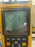
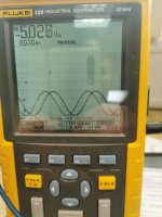
I don't think, that it is correct, to have the sine wave on the +-5v input for the drive board.. Can someone explain please.. It's also on the +-15v but only if I increase the gain. but only, if I use signal ground. If I use secondary, then it's normal.
Attachments
Last edited:
Did you ever check the value of the filter caps for the high-side B+ of the 21844?
Did you install a feedback resistor on terminals 1 and 2 of the TL072 when you were checking its signals?
Are you using a signal source with a grounded shield?
Did you install a feedback resistor on terminals 1 and 2 of the TL072 when you were checking its signals?
Are you using a signal source with a grounded shield?
You mean this small caps on the driver board? No, i dont. which value should they have?
No feedback resistor mounted. I always use a smartphone as audio signal. At home i have a fequency generator.
I can continue in a week, because again, both drivers are damaged...
No feedback resistor mounted. I always use a smartphone as audio signal. At home i have a fequency generator.
I can continue in a week, because again, both drivers are damaged...
With some amps, an ungrounded/floating shield can cause problems.
The caps for the high side have been from 4.7uF to 10uF. 5.6uF and 6.8uF seem to be the most common.
The caps for the high side have been from 4.7uF to 10uF. 5.6uF and 6.8uF seem to be the most common.
I checked the caps. One has 4.4uf the other 4.6uf..i think it is OK. Do they have a specific direction?
Most are ceramic which aren't polarized. That doesn't apply if they are tantalum or something other than ceramic.
- Home
- General Interest
- Car Audio
- GZPA 1.4000 DXII