Totally agree. I overlooked it....That's exactly what the buffer I showed you is..
Juma, I always wanted to use your pre with lower gain. You've stated somewhere in this thread that you've tested 6dB gain and it worked fine. Now I have 5.7dB.That's not going to work very good.
Don't get me wrong. I am not complaining. I think you are doing a great job.
All the noise issues are my fault (or my components). I have mentioned in some previous post that I like the sound of the preamp very much.
Yes, the first version with Schade feedback loop. The one you chose (with degeneration and output loading) is happier with with a bit more leeway.... You've stated somewhere in this thread that you've tested 6dB gain and it worked fine. ...
It's always beneficial to know what you want/need before starting a build. If you are not sure feel free to ask - also if you are too sure... 🙂
Yes, the first version with Schade feedback loop. The one you chose (with degeneration and output loading) is happier with with a bit more leeway.
I see.
Anyway, I am still a happy camper. I just need an F4 (maybe scaled down)
OK Just trying to get a feel for the environment. Might be worth having a read of Pano's article on gain structure http://www.diyaudio.com/forums/diyaudio-com-articles/186018-what-gain-structure.html
Tony.
Yes, I am aware of this article. It is also probably clear from what I have written above that I was aware of too much gain and my intention was to use the preamp with lower gain. Still as a first cut I wanted to try it as is. Even with this much gain I doubt Juma would be happy with this level of noise, so I still think there is some fault in MY build/components/power supply.
I had some poke with my oscilloscope yesterday but I got frustrated. I do not think it is up to the job.
Just out of curiosity I will try it with my TV setup (Musical Fidelity x-pre + some tripath T2024 (or so) and small bookshelf Mission 761 - probably less than 85dB). x-pre + tripath have also too much gain but there is no noise there.
And now I have another buffer to build;-)
Hi,
I have done some search on the net on measuring the noise in preamps. It looks like measuring with a cheap digital scope is hmm.. challenging (I knew that and I have checked that the hard way). I was thinking I need some preamp for the scope as well. It seems that is what people indeed do.
Am I on the right track? Has anybody done this with non professional equipment?
Hi Gregje, I was curious so did a sim on the cicuit. the gate stopper 220 ohm on the BS170 seems to be the largest contributor to noise in the circuit at around 80nV/hz in the sim... Note that I'm getting poor distortion performance much worse than what Juma reported, so the sim's value could be questionable.
edit: the 47R on collector of the bc550 also contributes around 30nV/Hz, the 47K around 8nV/Hz.
Perhaps replacing these with some high quality low noise resistors will help. Something like vishay dale cmf55's, probably worth a shot, especially if you are just using some generic resistors here,
Tony.
Last edited:
Hi Wintermute,
Thank you for your input. This weekend I played more with the oscilloscope. I prefer to do one thing at a time. I actually used a faster computer (the previous one should be still ok) which does not cause so many communication errors and I managed to get at least reliable voltage measurements from different points of the preamp. I can see some noise but I cannot say whether this is the real thing or the scope. I think it is the scope.
Thank you for your input. This weekend I played more with the oscilloscope. I prefer to do one thing at a time. I actually used a faster computer (the previous one should be still ok) which does not cause so many communication errors and I managed to get at least reliable voltage measurements from different points of the preamp. I can see some noise but I cannot say whether this is the real thing or the scope. I think it is the scope.
Yes one thing at a time is the best approach, Otherwise you don't know which thing made a difference if you do get a difference.
I lowered the 4.7 ohm resistor to 2.2 ohms in the sim (as per a previous post by Juma for reducing distortion) and the distortion in the sim became a lot more reasonable, so the noise results may also be reasonable.
Reducing the value of the gate stopper 220 on the bs170 also reduced the noise in the sim, but I don't know how low you can go without risking instability.
On the noise and the scope. The ground point you use can be quite critical. Try putting the ground point as close as possible to the output ground on your board.
Tony.
Hi
An update:
Ordering better gate stopper resistors (though the ones I have seem to be metal oxide according to my bill).
Tried to replace BS170 with 2N7000. No change. So by now I have tried to swap all active devices.
Listened to the preamp yesterday. I just love it. My perfectionist soul doesn't like the noise close to the tweeters, but as I've mentioned in my listening position I am fine.
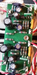
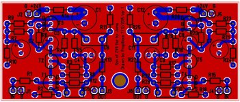
Hi Gregje: I was thinking that you might be interested in building the ver 1 of juma's preamp. As juma said, the ver 1 will like it better being set to 6 dB of gain, since that is all the gain you want/need. Below, in the pic of my build, the output caps are below. The sound is excellent. It is definitely better than coming straight from a D/A to the Aleph J. I replaced the Aleph J with a Cubie3 and it sounds even better to me. The bottom layer, shown in red, is a ground plane. If you are interested, I can email you the xgerber zip file. On the prototype pcb I had build, I forgot to check "Include top layer silkscreen", but it is there in the file. You can have a prototype pcb build at a low cost at PCB Pool in Ireland, I think, which is where I had that pcb made.
Attachments
Hi propitious,
Looks good! I was thinking about that, but for now I've started building the buffer Juma has suggested. It still might be interesting to build the earlier version of the present preamp.
I am also trying (slowly) to figure out why the present build is so noisy.
I have replaced the input 2M resistors with better ones. Still need to replace the gate resistors...
Someone else asked me for gerber files for version 1 that I drew. I thought I should say that I just finished drawing up a pcb for ver 2, which includes the power supply on a 110 x 60 mm pcb. I am about to get a prototype made to try out the design. So you might want to wait until then for this ver 2. It will accommodate different size output caps. For PS caps, I plan to use 1mF, low esr Panasonic, Nichicon, etc., though use any good cap larger if you want, if it fits. I put lead spacing sizes on the pcb. The bottom layer, shown in red, is a ground plane. A person may use the board with their own PS if desired.
Attachments


Hi guys
I have found the source of the noise!
These were 1M resistors at the gate of BS170...
Replaced them with new 1% precision 50ppm/K.
Before that I looked at 1M and 2M at the input but these did not have much effect on the noise.
What exactly is the purpose of these resistors? Cannot the 220Ohm gate stopper resistor take the reference voltage from the voltage divider R22/R23?
Anyway many thanks to everybody who has helped!
Wintermute: you directed me to look at the gate of BS170.
- Home
- Amplifiers
- Pass Labs
- Gyrator loaded Son of ZV9/F3