I built a test bed to evaluate different types of anode loads for my next version of the 12b4a preamp.
My current 12b4a preamp is using a 10m45s CCS as the load. It was a quicky to clean up the wiring mess I had initially, but some simple measurements of the frequency response showed it to be flat out past 30kHz.
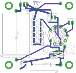
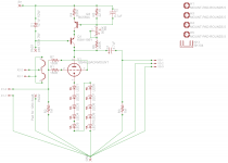
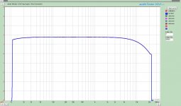
I am now playing with Wavebourn's Gyrator. Attached is the schematic, pcb used and the response curve. I don't think a gyrator has a response like this indicating I did something wrong. The response curve is shown with a calibration run so it is the circuit response that drops off starting at 10kHz. I have switched tubes, played with bias, and moved the anode voltage up and down. The curve is taken at 140V anode, 20mA bias with 200V b+ into the gyrator.
Your help would be greatly appreciated.
My current 12b4a preamp is using a 10m45s CCS as the load. It was a quicky to clean up the wiring mess I had initially, but some simple measurements of the frequency response showed it to be flat out past 30kHz.
I am now playing with Wavebourn's Gyrator. Attached is the schematic, pcb used and the response curve. I don't think a gyrator has a response like this indicating I did something wrong. The response curve is shown with a calibration run so it is the circuit response that drops off starting at 10kHz. I have switched tubes, played with bias, and moved the anode voltage up and down. The curve is taken at 140V anode, 20mA bias with 200V b+ into the gyrator.
Your help would be greatly appreciated.
Attachments

Last edited:
What is output & transfer capacitances summed of KSA1156Y?
What is input capacitance of your test equipment?
What is input capacitance of your test equipment?
Daft question, but I will ask anyway: are the grid stoppers actually 150? If you accidentally used 150K instead then you could get the HF rolloff due to Miller effect.
The input capacitance of the test equipment should be quite low. The cal curve was taken with the same set-up and cables. It is a 1626m soundcard.
In regard to the KSA1156Y I can't find the output or transfer capacitance in the fairchild spec sheet. I do have some MJE350STU on hand but I find the capacitances for those either.
DF96 good question will check.
In regard to the KSA1156Y I can't find the output or transfer capacitance in the fairchild spec sheet. I do have some MJE350STU on hand but I find the capacitances for those either.
DF96 good question will check.
Hello SGregory,
I do not have an answer. I do have a question.
How is the E-Mu and software set up? Setup in terms bits and frequency (16, 48), (24, 96) (?,?).
Could be the brick wall filter your plots are showing.
Does the same thing happen when you FFT your Salas JFET Riaa?
DT
All just for fun!
I do not have an answer. I do have a question.
How is the E-Mu and software set up? Setup in terms bits and frequency (16, 48), (24, 96) (?,?).
Could be the brick wall filter your plots are showing.
Does the same thing happen when you FFT your Salas JFET Riaa?
DT
All just for fun!
Last edited:
48kHz, 32bit. Filter shoould be about 22kHz as is shown on the red plot. I took that using direct feed through just before I measured the 12b4 (blue line). The output of the card is set to 1Vrms. Then attenuate it with a ladder attenuator to so that the output of the circuit is 1Vrms.
The Salas JFET Riaa was measured with the same set-up
The Salas JFET Riaa was measured with the same set-up
Here is some measurements
B+ 278V
V anode = 142V
With respect to B+:
The KSA1156 has 12.1V at its base, 136.2 at the collector, and 11.7V at it emitter.
The BC559C has 6.18V at its base, 11.7 at the collector and 5.53 at its emitter.
The zener diode is flowing 1.3mA
R5 is passing 0.28 mA
The circuit appears to be working, I suspect that the current may be too low through the zener for the ksa1156
Current was fine. Doubled it and still same rolloff.
Last edited:
C2 is an MKT. I will try a lower value.
After searching for a while, I have come to the conclusion the the capacitance of the KSA1156 has to be quite large. There is no documentation for it so it wasn't an issue in the design of the part. Found quite a few replacements that specify low capacitance but either they don't have a high enough voltage rating or can't dissapate enough heat. I know they are out there just havn't looked in the right spot yet.
After searching for a while, I have come to the conclusion the the capacitance of the KSA1156 has to be quite large. There is no documentation for it so it wasn't an issue in the design of the part. Found quite a few replacements that specify low capacitance but either they don't have a high enough voltage rating or can't dissapate enough heat. I know they are out there just havn't looked in the right spot yet.
What if to add some resistor to it's collector? Like, 1 KOhm, and see what happens (20V of voltage drop is not much).
Ok. tried lowering the value of C2. Results make sense in that the only thing effected was reducing the LF response.
I will try the 1k on the collector of the KSA next.
I will try the 1k on the collector of the KSA next.
I didn't have a 1 Watt 1k resistor so I used a 750R 3watt I had in the bin. (15V vs 20V, I didn't think it would matter too much) I still get the exact same HF roll-off. The curves lay right on top of each other
Attachments
Last edited:
Now, what if to take output from tube's grid? I mean, to check if it is Miller capacitance, or not.
You have narrowed this down thanks. I soldered a pin to the grid and measured.
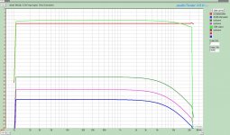
The bright green is the output of the preamp at 1Vrms out
The Red is the grid with no attenuation, howeever the bottom three lines is the grid with increasing attenuation. I have a 100k stepped ladder attenuator on the input. The Blue line is the attenuation needed to get 1Vrms at the output and where all of the testing to date has been done.
At this level the input impedance is 23.5k on the grid.
At that attenuation there is 75k in series with the signal
Attachments
Last edited:
Hello SGregory,
Hey that is a graphic demonstration of the Miller effect. The effect becomes more pronounced as the attenuator voltage divider shunts more signal to ground (my speculation).
What is the source driving the 12B4? It might not be just Mr. Miller if there is a coupling capacitor creating a time constant (low pass filter poll) with that 25K resistor in the atenuator to ground.
DT
All just for fun!
Hey DT,
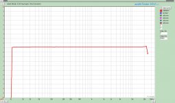
Something is certainly going on. Miller certainly is a candidate. I made a few more tests. This time I set the attenuator to full gain (zero attenuation). In otherwords it is now acting like a 100k grid leak resistor. I then dropped the input signal level so that the ouput level of the 12b4 was 1Vrms @ 1kHz.
I then repeated the sweeps.
The Red and Pink curves are of a calibration sweep and the measurement at the grid of the tube. No HF roll off this time on the input side.
I then swept measureing the output with and without the 750R resistor in the collector of the KSA. The roll-off is still there. (blue and green).
At least now I know it is not the input. The fact that the 750R resistor at the collector had zero effect points to something outside the circuit. Not sure yet how to test your point wrt a rc constant and Wavebourn's earlier comment regarding the input capacitance. I did switch cables with no change.
Attachments
Hello SGregory,
First thing when you take a deep breath and scratch your head and think.
That set of circuit testing tools on your bench is really cool for a home DIY guy to have to work with pat yourself on the back and say good job.
That wanabe choke, gyrator, thing is not intuitive to look at (perhaps needs a little tuning). Try the next item on your list, SRPP or whatever and come back to that thing. The Gyrator answer will dawn on you when you get out of bed next Tuesday.
Checkout this book, it may be of interest.
Amazon.com: How To Solve It: A New Aspect of Mathematical Method (9784871878302): George Polya, Sam Sloan: Books
DT
All just for fun!
Take a look at the IRFBC20. For a good sized, high voltage, power MOSFET, the capacitances are low and stable.
Hey DT,
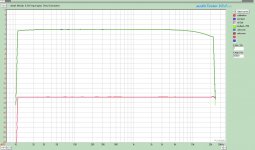
Had the same idea. Except my break was a shower. Came back and started thinking, Looked at my sound card and said "Why do they list the front input /Mic Input as HiZ?". So I switched to it and low and behold.......see attached.
Apparently the input on the back connectors is too low or has a high capacitance as Waveborne suggested. Will have to look at it in the morning.
Eli,
have thought about trying a FET and may whip up a board to try it before it is all over. I have a couple of BC20's left from the OPUS.
A Genuine and Heart Felt Thanks for those that helped me out.
Scott
P.S. Now to play around with the sample rate and see the higher frequencies
Attachments

- Status
- Not open for further replies.
- Home
- Amplifiers
- Tubes / Valves
- Gyrator Frequency Response?