To check at two different attenuation levels.
About right from what I measured on a bunch of different cables I had. Have a few AV cables that measure slightly better. Am reconfiguring my testbench to be able to employ very short leads to the soundcard and/or sound card interface depending on what I want to do.
About right from what I measured on a bunch of different cables I had. Have a few AV cables that measure slightly better. Am reconfiguring my testbench to be able to employ very short leads to the soundcard and/or sound card interface depending on what I want to do.
Last edited:
Will try to measure the Tracker with crapiest leads and pot I can find at top sampling rate to report back. Tomorrow.
Hello SGregory,
Congratulations! You may have found a way to test and demonstrate that $1000.00 interconnect cables make a difference. You should go over to that other thread and post your results.
DT
All just for fun!
Congratulations! You may have found a way to test and demonstrate that $1000.00 interconnect cables make a difference. You should go over to that other thread and post your results.
DT
All just for fun!
I am not touching that thread with a ten foot pole!!!!
The irony in this is tha two pieces of wire with alligator clips at the end performed the best!!!
The irony in this is tha two pieces of wire with alligator clips at the end performed the best!!!
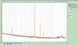
Here you are, this is Emu Tracker Pre at 192kHz 65536pts FFT, no flattening compensation file, looping itself in pink noise at 1/12 Oct resolution. Green is crappy 1.5m coax they throw in $29 DVD players, looping alone. Did not make a change to 10cm RG179. Red is plus a pot set at midpoint, and thin 30cm aligator clips to connect it. Pot is corroded open metal case $2 100K Ohm carbon. 100K is the most usual value to be found in a tube preamp. Thus red is 50K Rs driving 1Meg input in essence. Miller of a tube or Cinput of card forms RC. For neutral measurements of this kind, buffering is essential. Else, passive components interact freely with the loop parameters, for nominal values and/or extra capacitances they may carry.
Attachments
Thank you Nick. This confirms my data. Your explanation makes perfect sense on the importance of the interaction of cable capacitance on when dealing with higher impedances.
Even in DCB1 I spec 22K Log max because it limits BW (although far higher than here) and its a JFET buffer. Those high gm parts always have elevated Ciss & Crss. But the cable wasn't the problem in our example above. The high source resistance that the pot lend was. That is why buffered pots are better. Be it a DCB1 or my 6V6 bootstrapped cathode follower. Same story. Better than a pot alone.
Hello SGregory,
This has moved from interesting to insightful.
It no wonder a stepped attenuator followed by a cathode follower sounds better than a passive preamplifier.
DT
All just for fun!
This has moved from interesting to insightful.
It no wonder a stepped attenuator followed by a cathode follower sounds better than a passive preamplifier.
DT
All just for fun!
Passive is fine, provided the pot has a low resistance and the output cable is short. It also requires the next stage to have a high or linear input impedance - not always true. As in everything else, OK when used appropriately.
And then there is the drive thing. Even a 10K pot means 5K Rsource at half value setting. Keep that or current boost that, matter of application and receiver's demands.
No. 10K pot at halfway is 2.5K source, assuming it is driven from lowish impedance (which will normally be the case).
No. 10K pot at halfway is 2.5K source, assuming it is driven from lowish impedance (which will normally be the case).
Hello DF96,
If your post was intended to b e on topic I believe that you missed the point. The discussion was about attenuator resistance and interconnect capacitance forming a filter pole not power output.
DT
All just for fun!
Salas, In response to your post earlier regarding the noise of the zener. I did a little experiment before I switch out the zener with a couple of precision references. In the attached FFT plots, I compare the zener un-bypassed and bypassed. The cap used was a 220uF FC panasonic. 1V=0dB. I did not see a difference in this. I think I have a couple of precision references but haven't found them yet. Will post that when I do.
I am not sure what the hump is beteen 20k and 30k, but the unbypassed seem to perform better. The hump is part of the noise spectrum of the circuit. It is not present in the background FFT when I turn it off.
I am not sure what the hump is beteen 20k and 30k, but the unbypassed seem to perform better. The hump is part of the noise spectrum of the circuit. It is not present in the background FFT when I turn it off.
Attachments
Looks like being in the anode load circuit the lower circuit (tube) dominates for noise. Did you bypass the LEDS to also see?
No. 10K pot at halfway is 2.5K source, assuming it is driven from lowish impedance (which will normally be the case).
Still it represents some strong resistive addition to any source. If a transparent enough buffer will be used to interface it will make its presence felt IMO.
LEDS are still bypassed. I will run a couple of sweeps with and without they LED bypass. I could also incorporate a decent bypass for the caps and see if there is a measureable difference.
You got a very nice result for noise floor and THD anyway. But lets see all the parameters, its about knowing the circuit's practical behaviour.
Maybe, depends on the context. I was merely correcting a minor slip-up - 2.5K instead of 5K.Still it represents some strong resistive addition to any source.
I don't know why DT accuses me of being OT, as driving impedance for capacitance is one of the things we are talking about in this thread. Halving the impedance doubles the roll-off frequency.
- Status
- Not open for further replies.
- Home
- Amplifiers
- Tubes / Valves
- Gyrator Frequency Response?