With CCS the line goes almost horizontally. However, there will be some power drawn from the tube (otherwise why it is needed, right?), so the line should reflect load resistance.
I guess I was looking for a little more in depth explanation. I understand the line is help almost horizontally as the current is held constant no matter the voltage. Could you tell me how you go about selecting a load line with a CCS? If for example I selected my ccs to be at 100mA (your line is already there), it looks like a 0 input voltage would leave me at 100 volts. Using the formula you posted 350V (idle) - 100V (max current) = 250V swing. Am I right so far? If so, the opposite swing would be 350V (idle) +250v (swing) = 600V. The line at 600V doesn't meet my CCS load line. Can you tell me what that means and what is literally going on at that point? Would this be where I would decide that 100mA is to much and need to drop to 80-90mA?
Are there other matters you need to take into account with a CCS that you don't have to consider with a simple resistor?
From what I understand, the best sound comes from having the most equal distance between a load line and the tube curves, is this true? If so is there a simple way to find the most linear load line without measuring between each load line?
The best sound comes from equal change of output voltage and current per causing it change of input voltage. That means, if curves are taken for equal changes of grid voltage, you are looking for most equal lengths of parts of the line between points where it crosses the curves.
Speaking of CCS load line, it is the same as with choke/transformer load except voltage can't be higher than B+. Draw CCS - only load line (horizontal one), then add the line that corresponds to the resistance of the load that goes after the coupling capacitor.
Speaking of CCS load line, it is the same as with choke/transformer load except voltage can't be higher than B+. Draw CCS - only load line (horizontal one), then add the line that corresponds to the resistance of the load that goes after the coupling capacitor.
Last edited:
Thanks for making that clearer for me. I feel like I have a grasp on the concepts but I need to spend some time turning that into more real world experience.
Hi,
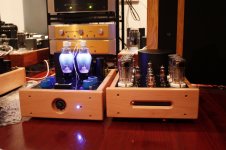
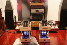
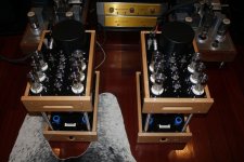
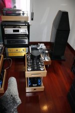
My setup is simply, Plate voltage about 440V ultralinear configuration plus cathode feedback. 50ma per tube (6 tubes). input tube diferential mode dual 6j43 plus sink current source; driver tube 6N6 CCS, 6N1 cathode follower output which provide individual bias for each final tube.
My setup is simply, Plate voltage about 440V ultralinear configuration plus cathode feedback. 50ma per tube (6 tubes). input tube diferential mode dual 6j43 plus sink current source; driver tube 6N6 CCS, 6N1 cathode follower output which provide individual bias for each final tube.
Attachments

banzas,
how about a little bit more info on your design. Like what transformers are you using. thanks tad
how about a little bit more info on your design. Like what transformers are you using. thanks tad
the output trafo is a vanderveen special version VDV2100CFB, the psu has dual voltage +/-180v for input tube (6P43) and cathode follower and like I said the the rail has 440v. The design hasn´t nothing special, it is all simetric and the input tube is a great performer.
Attachments
- Status
- Not open for further replies.
- Home
- Amplifiers
- Tubes / Valves
- GU-50 in Single-Ended Triode Configuration - What bias points?