Thanks, Jan - that is very good info to know !
The big film caps with my EL84 amp stem from my previous version where I wanted to build an (unregulated) tube amp PSU without electrolytics 😱
I see that after the regulator you want caps with some losses to improve stability. That reminds of the threads around the VRDN supply and Mark Johnson's SMPS filters. Does it hold for unregulated supplies, and for solid-state PSUs as well that filter and decoupling caps with some losses are preferred ?
Best regards, Claas
Hi, I'm putting together a parts order while I wait for my T-Reg V5 kit to arrive and I'm puzzled by the BOM listing of D7 and D8. In your May 2020 blog post you stated
However, the BOM for V5 has D7 and D8 as BAT42s. I imagine this is just an oversight. If you think about it, these days the term 2020 hindsight has an entirely different meaning.
Also, I find that Mouser may not carry as wide a selection of high voltage metal foil resistors as Digi-Key. For my 1963 HH Scott 222C, which puts 445V out of the 5AR4 rectifier, I figure the correct value for R11 to be approximately 767kOhms. Digi-Key has a larger range of Vishay's HVR25 series which tolerate up to 1600VDC. I've found they have one at 768kOhm, which is surprisingly close. (Part # PPCQF768KCT-ND). At 43 cents it's a bargain compared at what I found trudging through Mouser for various combinations that would get me there, although it will incur an additional shipping cost.
Previously I suggested BAT42 diodes here, but I now recommend SB140-T Schottky diodes, Mouser 621-SB140-T. There should be no problem to put them both on the current PCB but I will adapt the next version of the board for proper layout.
However, the BOM for V5 has D7 and D8 as BAT42s. I imagine this is just an oversight. If you think about it, these days the term 2020 hindsight has an entirely different meaning.
Also, I find that Mouser may not carry as wide a selection of high voltage metal foil resistors as Digi-Key. For my 1963 HH Scott 222C, which puts 445V out of the 5AR4 rectifier, I figure the correct value for R11 to be approximately 767kOhms. Digi-Key has a larger range of Vishay's HVR25 series which tolerate up to 1600VDC. I've found they have one at 768kOhm, which is surprisingly close. (Part # PPCQF768KCT-ND). At 43 cents it's a bargain compared at what I found trudging through Mouser for various combinations that would get me there, although it will incur an additional shipping cost.
Both the BAT42 or the SB140-T diodes will work fine. They are limiting the voltage between the opamp pins and normally are not conducting.
I recommended the SB2140-T because they allow slightly higher currents, but if you mounted the BAT's, just leave them be.
I'll check the BOM.
Jan
I recommended the SB2140-T because they allow slightly higher currents, but if you mounted the BAT's, just leave them be.
I'll check the BOM.
Jan
Oh, and just one more thing..... (I've been watching a lot of Columbo episodes during this pandemic.)
There's a discrepancy between the V5 BOM and the schematic. The BOM calls for Q2, Q3 to be BC550C and Q5 as BC560C. On the schematic, you have designated BC546B for Q2 and Q3, and BC556B for Q5.
The BC550C and BC560C are now becoming obsolete as are BC546B and BC556B, and may not be stocked, depending on which supply outfit you use. I compared the BC546C and the BC556C data sheets and those look like they're acceptable substitutions.
Yeah it's hard to keep track of what comes and goes.
Basically, any small signal TO-92 transistor of the right polarity will work. 100mA, 30V, Hfe > 150, which practically a zillion types fill.
Jan
Basically, any small signal TO-92 transistor of the right polarity will work. 100mA, 30V, Hfe > 150, which practically a zillion types fill.
Jan
Just think of this as a loosely organized peer review system. In academe, research assistants would do the donkey work on such things to leave more time for the eggheads to nap.
Is there any advantage to having a choke before the T-reg, such as
CLC(reg)C, or go straight to the T-Reg from the main filter cap? (assuming the input voltage/ripple is sufficient to keep the regulator happy)
CLC(reg)C, or go straight to the T-Reg from the main filter cap? (assuming the input voltage/ripple is sufficient to keep the regulator happy)
The exact scientific answer: anything that you do before the regulator changes the output by some number of electrons;
My answer: the performance of the T-reg is such that you will not hear any difference from filters or pre-regulators before it. In fact, additional stuff may worsen the sound due to additional ground loops and EMI ingress points;
The audiophile answer: I inserted a coil from Acme Audio Research before the T-reg and the sound really opened up, night and day!
Your call ;-)
Jan
The lower the current the larger the limit resistor value.
From the build guide:
How to set the current limit
A single resistor, R16, needs to be selected to set the current limit. Current
limiting occurs when the voltage across R16 gets to about 0.8V. So, for example,
if you want a current limit of 180mA, your R6 will be 0.8/0.180 = 3.3Ω.
Jan
Is this example correct? 0.8/0.180 = 4.4ohm.
Sorry for nitpicking but this confused me a bit.
You are absolutely correct, it is 4.4 ohms nominal, I goofed.
Thanks for the heads-up! I will correct the writeup.
Jan
Thanks for the heads-up! I will correct the writeup.
Jan
I'm a bit confused about the intended use of this regulator. It makes sense that everything following after the regulator compromises it's performance so it should be connected close to it's load. It seems that different users had problems connecting it to interstage or output transformers directly and that the regulator is unstable with an inductive load?
That leaves a use in single stage buffers ("line stages") with anode resistors as loads.
Is that correct?
That leaves a use in single stage buffers ("line stages") with anode resistors as loads.
Is that correct?
Yes, post #241 ff for example, the issues Derek is/was (?) having.
In post #247 you wrote:
"I believe that the problem with the large inductive load is the fact that an inductor tends to create a large varying voltage with varying current. If that voltage gets above the T-reg output, it can't 'go' anywhere - a regulator is designed to source current, not to sink it."
That would leave shunt regulators as the only option to directly connect them to transformer primaries or anode chokes.
When you refered to 53H (post #245) as "large inductive load", what would be a "safe inductive load" for your regulator?
(my apologies if this sounds like I was looking for an argument)
Hallo schiirn,
for what it's worth, with one sample of this regulator I'm powering an Aikido line stage (can be configured both as a buffer and as an Aikido with gain, the regulator works well with both).
With the other sample I'm powering the B+ of a complete EL84 push-pull amplifier. Yes, that one is capacitor-coupled, so no interstage transformers, but it has big output transformers nevertheless, and burns more than 45W in the high-voltage section. The regulator works very well here also.
Regards, Claas
Yes, post #241 ff for example, the issues Derek is/was (?) having.
In post #247 you wrote:
"I believe that the problem with the large inductive load is the fact that an inductor tends to create a large varying voltage with varying current. If that voltage gets above the T-reg output, it can't 'go' anywhere - a regulator is designed to source current, not to sink it."
That would leave shunt regulators as the only option to directly connect them to transformer primaries or anode chokes.
When you refered to 53H (post #245) as "large inductive load", what would be a "safe inductive load" for your regulator?
(my apologies if this sounds like I was looking for an argument)
Ahh yes, but you have to discern between a series choke after the T-reg, or the load presented by an (interstage) transformer.
A series choke may be troublesome, but it should be noted that using a series choke after a regulator doesn't make any sense anyway. It's a waste of money and space. If you are religious about chokes, put it before the regulator, that can make sense.
An (interstage) transformer should be no problem as it isn't an inductor but reflects the secondary load to the primary and the regulator and that load is normally not inductive.
In the previous pages there are some reports with successful use of T-reg and a transformer.
Jan
"A series choke may be troublesome, but it should be noted that using a series choke after a regulator doesn't make any sense anyway. It's a waste of money and space. If you are religious about chokes, put it before the regulator, that can make sense."
How does it make sense to take the high Z anode load and replace it with a low Z regulator and then put that high Z inductor before the regulator???
This all remains very confusing.
How does it make sense to take the high Z anode load and replace it with a low Z regulator and then put that high Z inductor before the regulator???
This all remains very confusing.
Attachments
An (interstage) transformer should be no problem as it isn't an inductor but reflects the secondary load to the primary and the regulator and that load is normally not inductive.
In the previous pages there are some reports with successful use of T-reg and a transformer.
Jan
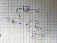
"Should be no problem" and "some reports with successsful use" still make it sound as if something like the attached schematic might or might not work...
Attachments
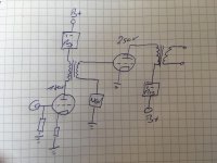
I only say that because I have not tested it myself. But your schematic will work well.
Jan
Jan
Last edited:
- Home
- Group Buys
- Group Buy for Jan's high voltage regulator