Sorry Sextaafondo, my comment was not directed at the ground scheme or any of the advice you have given. I agree with you, changing the ground scheme has not removed the hum because there are other problems and that the best way of locating the problems is to test each part independently.
Mark, I repeat: I know where both the buzzing and the white noise are introduced respectively, I just don't know how to remove them (having the volume pot on the back of the amp obviously isn't an option, and I'm starting to think the white noise is just intrinsic to the P101 design) without rebuilding the entire amp. I really don't see what I would stand to gain by taking everything out of the chassis. I can get the buzzing to disappear completely by placing the pot behind the amp, and the white noise is there no matter what I do, even when the amp is running on the remaining charge in the filter caps with everything else turned off (and I've also tried disconnecting everything preamp related from power, that didn't change anything either), so I'm positive it's produced/picked up in the P101 and there's no way to get rid of it without changing the P101 schematic/board. The white noise is not really an issue for me since it's so quiet you really have to go after it by connecting IEMs to the output or pressing your ear against the speaker in a quiet room. The same goes for the buzzing, it's also very quiet, but there I know it should be possible to get rid of it, so it bugs me a bit more. However I know it's just a component placement issue at this point and I'm not ready to do another rebuild of this amp just to get rid of an extremely quiet buzzing that won't ever bother me while listening to music.
The semester is starting soon, so the student lab will be back to regular opening hours. I'll take some measurements and calculate a proper SNR then - I'm fairly certain it'll be rather low when taking into account the voltage swing the amp is capable of.
@sextaafondo: The ground connections are already set up the way you described - the two exceptions are that the P101 input ground is connected to the pot's ground and that I separated the preamp ground from P101 ground. These were made because having the P101 input ground go directly to star ground caused a ton of buzzing due to the large loop and I found that separating preamp ground (which is implemented in a star ground layout as well, btw - easy because there's only two wires that connect to it) and P101 ground improved the buzzing a tiny bit. Another exception I guess would be the wire connecting the two grounds on the P101 board but I know for sure that's not causing any buzzing because relocating the pot or shorting the input directly on the board both solve the buzzing issue, and I'd rather not mess with Rod's design more than necessary. And I'm pretty sure it's not picking up the white noise either.
Edit: I just thought of one possible (and practical) way to combat the buzzing: Moving the pot further to the right, away from those nasty transformers. I'll try that later today and if it helps, I'll have to order a new frontplate that I'll drill to accomodate the pot at a better spot.
Last edited:
Edit: I just thought of one possible (and practical) way to combat the buzzing: Moving the pot further to the right, away from those nasty transformers. I'll try that later today and if it helps, I'll have to order a new frontplate that I'll drill to accomodate the pot at a better spot.
Cool; keep us posted!
You could move the pot to the middle of the amp with an extension rod to the front.
Philip Jackson's HiFi DIY Project - Second Amplifier Page
Link to a P101 build with transformer and PSU compartment within one chassis.
Philip Jackson's HiFi DIY Project - Second Amplifier Page
Link to a P101 build with transformer and PSU compartment within one chassis.
Alright, so I tried placing the pot further to the right and while it makes the buzzing a bit better, it's still there - not worth a new frontplate.
Mark, that's actually a great idea - I think I'll get one of those extension shafts from Rod, I have to buy some P33 boards from him anyway and having the pot between the preamp and the right channel P101 board will make for some neat and short cabling! I guess this means I'll have to get a new frontplate after all, but at least it'll be worth it!
Mark, that's actually a great idea - I think I'll get one of those extension shafts from Rod, I have to buy some P33 boards from him anyway and having the pot between the preamp and the right channel P101 board will make for some neat and short cabling! I guess this means I'll have to get a new frontplate after all, but at least it'll be worth it!
Well, it's been a while but I've been busy making another amp (ClaveFremen's My_ref FE) and only now got around to working on the P101 again. I also fried one of the boards when I accidentally reversed the supply polarities after a long night of fiddling with the amp, so it took me a while to get new output transistors and all the other stuff that ended up blown. Now, it's done however and I have (yet again...) changed some other things too:
-When I fixed the second channel, I replaced all transistors on both sides with matched pairs (apart from the power FETs) - it turned out that two of the MOSFET source resistors had burned out too, causing the broken channel to malfunction even after all actives had been replaced. I took the opportunity to replace all the current sharing resistors with 5W wirewound (at least I think they are) types that I sourced locally.
-Instead of having the signal go input->preamp->pot->P101 (which was really dumb in retrospective), it's now the usual input->pot->preamp->P101 setup.
-I added a ground loop breaker and moved the star ground point to the ground rail of the filter cap bank, which has given rise to some wiring layout issues. I used the bridge rectifier/resistor/capacitor circuit described by Rod Elliott in his grounding guide.
-I wrapped all the small signal wires with exception of the short pre->power amp ones in copper tape to shield them, the "shields" are connected to the new star ground point (I had them connected to the chassis/earth ground first but that seemed to cause some problems). I also shielded as much of the pot as I could (basically everything but the underside), and for testing purposes I tried shielding the untwisted part of the left speaker return line as well (didn't tape it up with electrical tape though), but that has not produced any improvement or other change as far as I can tell.
-I swapped the input caps (Russian NOS K71-4) for some smaller ones of the same value (Russian NOS K73-16), scratched a bit of the coating off the metal cans and wrapped that with copper foil and grounded it as well, as the metal casing caused buzzing with shorted inputs when not grounded. I have pictures of this process if anyone's interested but it's pretty straightforward really.
Now, here are the issues I'm still facing:
-The loop breaker does not have the desired effect - when connecting my USB powered pupDAC to the input, I still get rather loud buzzing. It's quieter than with the amp's ground shorted to chassis/earth, but it's still there. Removing the safety earth connection fixes this entirely (as expected), as does keeping the amp ground floating but having the chassis connected to earth.
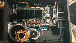
-With its input shorted, the left channel produces audible (by audible I mean with headphones or earbuds, not necessarily on the speakers) buzzing - more than with the input connected, even. I can reduce it a lot by moving around the speaker return wire. I'm not sure whether the buzzing is caused by inductive coupling from the PSU wires to the speaker return or just by proximity to the big transformer. But I haven't managed to kill the buzzing completely with that method. On the other hand, the right channel is almost perfectly quiet (using 32 ohm earbuds directly at the output) when I short the input. I have no idea what is causing this behavior, but the left channel is much closer to the power supply parts (see pic) so that might have something to do with it.
-With the P101 inputs connected to the preamp (which in turn has its inputs shorted by the pot), the left channel still buzzes "by default", but it is noticeably quieter than with a shorted input and I can position the speaker return wire so that it becomes almost entirely quiet (see picture) - the same level as the right channel with a shorted input. The right channel also develops a slight buzz with connected inputs, but I'm not sure whether it changes with wire position as my wires are so short and thick that I can hardly move them. This is all with the vol. pot set to zero, by the way.
And now to my actual questions:
-Should I leave out the ground loop breaker and leave the amp's ground floating (this causes some issues, for example touching the chassis gives a bit of hum), or is there a way to improve its efficacy? Can I just increase the breaker resistor's value (and if so, how high can I go while retaining the circuit's intended function?)?
-How should I best arrange the PSU and speaker return wires for minimum buzzing? I'm unsure whether it would be wiser to group/twist them together such that a group of wires carries 0 total current - that would mean runnung the speaker return and all 3 PSU wires to the capacitor bank/ground point together - or just to isolate the signal wires as much as possible and route them as far away from the transformer as possible.
-Can anyone offer a theoretical explanation as to why the left channel gets MORE buzzing with shorted inputs whereas the right channel behaves the opposite way? I'm really struggling to understand this.
-After determining which wires I'm gonna run together, would attempting to shield the wire groups with the copper foil do any good? I've been going a bit overboard with this stuff as you can see from the massive input/output "wiring harness" going to the pot 😀
And here are the pics:
This is how the left channel produces minimum buzzing - I'm not sure if there's even any buzz left as I can't distinguish it from the background white noise even with earbuds hooked up directly to the output. The wire with the copper tape around it is the speaker return line and the three to the left are the DC supply lines.

And here's how to get maximum buzz volume - still not extremely loud, but certainly noticeable:

As mentioned, the right channel's buzzing hardly changes with wiggling the wires (might just be because there's hardly any wiggle room to begin with), but I'm rather sure the buzzing is caused/picked up by the speaker return/PSU wires, because arranging the left channels' wires as shown in the first pic results in way less buzzing than I get on the right one with both channels' inputs connected respectively, and since the left and right small-signal cables are routed exactly the same all the way to the preamp, it would be odd for only one channel to pick up noise. But it's weird that shorting the inputs should fix it entirely on the right channel whereas the opposite happens on the left.
And here are the links to the full-size images - I know some people don't like big images embedded in posts so I downsized them a bit.
min. buzz: http://i.imgur.com/994poHv.jpg
max. buzz: http://i.imgur.com/BSBRfKR.jpg
P.S. I copy/pasted this post with some minor editing from a post I made on the ESP forums, so if something doesn't make sense or isn't explained right in this thread let me know.
-When I fixed the second channel, I replaced all transistors on both sides with matched pairs (apart from the power FETs) - it turned out that two of the MOSFET source resistors had burned out too, causing the broken channel to malfunction even after all actives had been replaced. I took the opportunity to replace all the current sharing resistors with 5W wirewound (at least I think they are) types that I sourced locally.
-Instead of having the signal go input->preamp->pot->P101 (which was really dumb in retrospective), it's now the usual input->pot->preamp->P101 setup.
-I added a ground loop breaker and moved the star ground point to the ground rail of the filter cap bank, which has given rise to some wiring layout issues. I used the bridge rectifier/resistor/capacitor circuit described by Rod Elliott in his grounding guide.
-I wrapped all the small signal wires with exception of the short pre->power amp ones in copper tape to shield them, the "shields" are connected to the new star ground point (I had them connected to the chassis/earth ground first but that seemed to cause some problems). I also shielded as much of the pot as I could (basically everything but the underside), and for testing purposes I tried shielding the untwisted part of the left speaker return line as well (didn't tape it up with electrical tape though), but that has not produced any improvement or other change as far as I can tell.
-I swapped the input caps (Russian NOS K71-4) for some smaller ones of the same value (Russian NOS K73-16), scratched a bit of the coating off the metal cans and wrapped that with copper foil and grounded it as well, as the metal casing caused buzzing with shorted inputs when not grounded. I have pictures of this process if anyone's interested but it's pretty straightforward really.
Now, here are the issues I'm still facing:
-The loop breaker does not have the desired effect - when connecting my USB powered pupDAC to the input, I still get rather loud buzzing. It's quieter than with the amp's ground shorted to chassis/earth, but it's still there. Removing the safety earth connection fixes this entirely (as expected), as does keeping the amp ground floating but having the chassis connected to earth.
-With its input shorted, the left channel produces audible (by audible I mean with headphones or earbuds, not necessarily on the speakers) buzzing - more than with the input connected, even. I can reduce it a lot by moving around the speaker return wire. I'm not sure whether the buzzing is caused by inductive coupling from the PSU wires to the speaker return or just by proximity to the big transformer. But I haven't managed to kill the buzzing completely with that method. On the other hand, the right channel is almost perfectly quiet (using 32 ohm earbuds directly at the output) when I short the input. I have no idea what is causing this behavior, but the left channel is much closer to the power supply parts (see pic) so that might have something to do with it.
-With the P101 inputs connected to the preamp (which in turn has its inputs shorted by the pot), the left channel still buzzes "by default", but it is noticeably quieter than with a shorted input and I can position the speaker return wire so that it becomes almost entirely quiet (see picture) - the same level as the right channel with a shorted input. The right channel also develops a slight buzz with connected inputs, but I'm not sure whether it changes with wire position as my wires are so short and thick that I can hardly move them. This is all with the vol. pot set to zero, by the way.
And now to my actual questions:
-Should I leave out the ground loop breaker and leave the amp's ground floating (this causes some issues, for example touching the chassis gives a bit of hum), or is there a way to improve its efficacy? Can I just increase the breaker resistor's value (and if so, how high can I go while retaining the circuit's intended function?)?
-How should I best arrange the PSU and speaker return wires for minimum buzzing? I'm unsure whether it would be wiser to group/twist them together such that a group of wires carries 0 total current - that would mean runnung the speaker return and all 3 PSU wires to the capacitor bank/ground point together - or just to isolate the signal wires as much as possible and route them as far away from the transformer as possible.
-Can anyone offer a theoretical explanation as to why the left channel gets MORE buzzing with shorted inputs whereas the right channel behaves the opposite way? I'm really struggling to understand this.
-After determining which wires I'm gonna run together, would attempting to shield the wire groups with the copper foil do any good? I've been going a bit overboard with this stuff as you can see from the massive input/output "wiring harness" going to the pot 😀
And here are the pics:
This is how the left channel produces minimum buzzing - I'm not sure if there's even any buzz left as I can't distinguish it from the background white noise even with earbuds hooked up directly to the output. The wire with the copper tape around it is the speaker return line and the three to the left are the DC supply lines.
And here's how to get maximum buzz volume - still not extremely loud, but certainly noticeable:
As mentioned, the right channel's buzzing hardly changes with wiggling the wires (might just be because there's hardly any wiggle room to begin with), but I'm rather sure the buzzing is caused/picked up by the speaker return/PSU wires, because arranging the left channels' wires as shown in the first pic results in way less buzzing than I get on the right one with both channels' inputs connected respectively, and since the left and right small-signal cables are routed exactly the same all the way to the preamp, it would be odd for only one channel to pick up noise. But it's weird that shorting the inputs should fix it entirely on the right channel whereas the opposite happens on the left.
And here are the links to the full-size images - I know some people don't like big images embedded in posts so I downsized them a bit.
min. buzz: http://i.imgur.com/994poHv.jpg
max. buzz: http://i.imgur.com/BSBRfKR.jpg
P.S. I copy/pasted this post with some minor editing from a post I made on the ESP forums, so if something doesn't make sense or isn't explained right in this thread let me know.
Last edited:
Just attach your pics.
Then we all get to see them even after your remote server has died.
What is the yellow wire that passes the input sockets?
It starts off as twisted then finishes it's journey alone !
What is the copper? tube?
Is that a Main Audio Ground on top of the PSU capacitors?
Then we all get to see them even after your remote server has died.
What is the yellow wire that passes the input sockets?
It starts off as twisted then finishes it's journey alone !
What is the copper? tube?
Is that a Main Audio Ground on top of the PSU capacitors?
Last edited:
The yellow wire is a speaker return line (I'm assuming you're talking about the left one), which goes directly to the star ground point as specified by Rod. It doesn't actually run very close to the input sockets, just looks that way from the angle of the picture.
The copper is just thin copper foil with adhesive on one side, you can buy it on ebay for pretty cheap. The copper tape around the left channel's speaker return line isn't going to stay like that permanently, I'm either gonna tape it up with isolating tape or remove it altogether - obviously having grounded metal run all over the place is rather risky.
And yes, the P101 star ground point is on the ground rail of the filter caps (again, as recommended by Rod himself).
Last edited:
The Speaker Return current Route MUST follow the Speaker Flow Route all the way.
It must NEVER get separated to run alone !!!!!!!!!!!!
There are many recommending that the Main Audio Ground MUST NOT be located on the PSU smoothing caps link.
I am one of them.
You MUST change those two fundamental wiring errors.
It must NEVER get separated to run alone !!!!!!!!!!!!
There are many recommending that the Main Audio Ground MUST NOT be located on the PSU smoothing caps link.
I am one of them.
You MUST change those two fundamental wiring errors.
Well, that's where the root of my confusion lies - the speaker output is on the amp board, and the speaker return line must go to the star ground. So if I'd have to run my speaker return wire together with the supply lines (as that's where the current for the speaker originally comes from), but I'm not sure if that's really the way to go. Add to that the fact that on the left channel, separating the supply lines from the speaker return wire increased the noise - that may well have been due to the proximity to the big transformer though.The Speaker Return current Route MUST follow the Speaker Flow Route all the way.
It must NEVER get separated to run alone !!!!!!!!!!!!
Follow the Speaker current from the PSU all the way to the speaker.
Since you are using a push-pull output stage the route for the +ve current is very slightly different to that of the -ve current. but both the alternate routes are physically very close, or should be if your layout places the two output devices right next to each other.
Remember the PSU is a SOURCE and all the current coming OUT of that Source MUST RETURN to that Source.
That why the Speaker Return route must return to the PSU.
BUT, to minimise interference the Return Route must maintain low loop area all the way back, not just half of the route.
I went ahead and twisted the speaker return lines together with the supply wires and pulled the left channel's V+/V- wires through the "ground tube". I don't think the amp's gonna get any better than this - I can hear a tiny bit of buzzing with earbuds connected directly to the output, but it's so quiet that I can hardly tell it apart from the white noise and I think it's just power supply ripple getting through to the input stage. The fact that the noise is the same on both channels is also reassuring. The speakers are dead quiet apart from a bit of unavoidable white noise that can only be heard when pressing ones ear directly to the tweeter. I might shield the twisted wire groups with the copper tape later on for good measure.
What's bugging me now is the fact that the big power transformer itself is buzzing - I'm not sure whether we have some DC on our mains lines or if the transformer is just not wound tightly enough. I never noticed it this strongly before. I might go ahead and splurge on one of these:
http://sklep.toroidy.pl/en_US/p/TTSA0500-Transformer-AUDIO-TSA500VA-voltage-to-50-V/319
And maybe wrap it in mu-metal/permalloy to kill any hum it might induce.
First I have to add a speaker protection circuit though, so the amp will at least be comfortably usable without having to unplug the speakers before turning it on every time.
Also, any advice on the ground loop breaker would be appreciated - should I just replace the 10R with 100R or thereabouts, or am I better off leaving the amp ground floating?
Edit:
I was writing my post when you posted - thanks for the help, you were spot on!
Attachments
Last edited:
You are not allowed to leave exposed conductive parts "floating".
The rules are
The chassis must be connected to the Protective Earth.
All exposed conductive parts should be connected to the (protected) Chassis.
The rules are
The chassis must be connected to the Protective Earth.
All exposed conductive parts should be connected to the (protected) Chassis.
Now move the Main Audio Ground (MAG) off the PSU.
Use a single wire to connect the PSU Zero Volts to the (new) MAG.
Use a single wire to connect the PSU Zero Volts to the (new) MAG.
You are not allowed to leave exposed conductive parts "floating".
The rules are
The chassis must be connected to the Protective Earth.
All exposed conductive parts should be connected to the (protected) Chassis.
Chassis is grounded to earth now, but connecting my PSU/amp ground to the chassis results in the most horrible ground loop when using sources powered by my PC's USB bus - the loop breaker in its current form (bridge rectifier, 100nF cap and 10 ohm resistor as described here: Earthing (Grounding) Your Hi-Fi - Tricks and Techniques) seems to do very little to prevent that, which is why I'm wondering if I can just use a larger resistance to help break the loop.
What purpose would that serve? And, more importantly, what would I even need to connect to this main audio ground? The speaker returns?AndrewT said:Now move the Main Audio Ground (MAG) off the PSU.
Use a single wire to connect the PSU Zero Volts to the (new) MAG.
Also, note that that's pretty much the setup I had before I moved the ground point to the PSU and there was definitely more buzzing then. On the other hand, my wires were not as tightly twisted as they are now so that was probably at least part of the reason.
Last edited:
the Main Audio Ground is where all the circuits get their "reference" to allow the various parts to works together.
It must not be on the PSU Zero Volts link.
It must not be on the PSU Zero Volts link.
Rod Elliott recommends placing the star ground point on the PSU ground rail and it seems to be working fine for me too - what would be the problem with having it there, in your opinion?the Main Audio Ground is where all the circuits get their "reference" to allow the various parts to works together.
It must not be on the PSU Zero Volts link.
Charging pulses across the zero volts link contaminate the "point".
The classic symptom of this wiring error is buzz !!!!
Don't do it.
The classic symptom of this wiring error is buzz !!!!
Don't do it.
Ah, I believe I should be fine then, because the transformer center tap is connected to the ground bus on the other side of the tube. The point where the amps and speakers get their ground reference only has "audio grounds" connected to it (except for the shield grounding wire) so there shouldn't be any charging currents flowing there.
Try running a wire from the board's speaker output pin twisted with the speaker return all the way to the connection at the star point. Just leave that end of the speaker wire open. This will most likely kill inductions at that return wire running alone.
- Status
- Not open for further replies.
- Home
- Amplifiers
- Solid State
- Grounding issues with P101, RK27 and The Wire