What I was trying to do was give an engineering approach to your problem. One channel, one amp, with no ground loops and small loop areas, No Hum. Your method of randomly trying things has not worked so far.
What I was trying to do was give an engineering approach to your problem. One channel, one amp, with no ground loops and small loop areas, No Hum. Your method of randomly trying things has not worked so far.
And I appreciate that, but you have to realize that the picture you posted corresponded precisely to the way I had the amplifier set up before changing to sextaafondo's approach - I've had the second channel disconnected from power for quite a while and before connecting the speaker return directly to the PSU (which resulted in no change to the hum) my wiring was exactly the same as your corrected picture. There were no superfluous ground connections, no ground loops and small loop areas were a given anyway since I used twisted-pair cable for all signal connections. Unfortunately, the hum persisted.
Furthermore, I was randomly trying things because, before sextaafondo, no one had made any suggestions that didn't match up with something I had already tried. His approach has gotten me closer to having no hum than I've ever been before, and unlike before, we have a pretty decent idea of what is causing the hum.
Also, using the shield as the return connector wasn't/isn't me "randomly trying" things. It was a (pretty successful) try to minimize loop area. Using the twisted-pair shielded cable to carry the stereo signal with the shield serving as the pot ground's ground line is the same thing - having the return connection right around the signal wires minimizes the loop area formed by that signal connection. I believe that you will not find any engineering faults in the concept - it's just a star ground topology combined with minimal loop area for the small-signal connections.
Last edited:
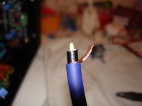
Well, it seems I finally got it right! Having the preamp->pot wires and pot->star ground return integrated in one shielded cable leaves only a tiny bit of buzz - part of it picked up by the pot->P101 cable (this disappears when putting it in the right position), the other part picked up by the new preamp->pot cable, but this also goes away when positioning the cable right, leaving behind nothing but beautiful silence!! I'm going to have to find the perfect positions for the cables and tape them there or something.
Here's a pic of the working thing - only one channel is connected as of now:

You can also see I had to deviate from a "true" star ground a little bit with the preamp - having the Wire amp board connected to star instead of its PSU directly was giving me some hum.
One thing that's still bothering me is that on turn-on, I get quite a loud "thump" that looks pretty painful for the speaker's membrane. This only happens with earth ground connected to star/chassis. Is there any way to stop this from occurring?
Here's a pic of the working thing - only one channel is connected as of now:
You can also see I had to deviate from a "true" star ground a little bit with the preamp - having the Wire amp board connected to star instead of its PSU directly was giving me some hum.
One thing that's still bothering me is that on turn-on, I get quite a loud "thump" that looks pretty painful for the speaker's membrane. This only happens with earth ground connected to star/chassis. Is there any way to stop this from occurring?
Last edited:
I'm glad you are finally able to see the light at end of the tunnel 🙂
It's OK to implement the mods you are saying to the ground scheme. In fact I was about to suggest you the same. The former scheme was proposed in order to make a drastic change in the previous ground configuration; that way you'd be able to tell if it was better or worse.
My amp has LME49830 input chips with 2 possible ground connections and independent from the rest of the amp. I'm also using the cable shield to provide ground to the LME circuit.
Though they occupy a lot of space, I chose a really good shielded wire. The wires you're using are more prone to noise pickup.
If you can, re arrange the components location inside the enclosure to a more suitable one. The transformer and rectifiers at the back, and the boards at the front near the pot.
Keep us posted. I'm sure this is of interest to lots of people.
Attachments
From what I can see, you did not connect the signal return from the pot to star GND as sextaafondo had advised, but connected it to the P101 input GND.
Good news that you are seeing some improvements and keep us up to date.
Good news that you are seeing some improvements and keep us up to date.
Last edited:
I'm glad you are finally able to see the light at end of the tunnel 🙂
It's OK to implement the mods you are saying to the ground scheme. In fact I was about to suggest you the same. The former scheme was proposed in order to make a drastic change in the previous ground configuration; that way you'd be able to tell if it was better or worse.
My amp has LME49830 input chips with 2 possible ground connections and independent from the rest of the amp. I'm also using the cable shield to provide ground to the LME circuit.
Though they occupy a lot of space, I chose a really good shielded wire. The wires you're using are more prone to noise pickup.
If you can, re arrange the components location inside the enclosure to a more suitable one. The transformer and rectifiers at the back, and the boards at the front near the pot.
Keep us posted. I'm sure this is of interest to lots of people.
Hey man, first of all thanks a lot - I wouldn't have had the idea of such a consequent star grounding scheme.
That cable really does look pretty awesome/expensive, what brand/kind is it? I'll see if I can get some really good stuff at my electronics store, but even if I can't, I'm pretty sure I can get it to be quiet by positioning the cables right.
About redoing the component placement: The thing is that I've already done that once (obviously that was work I did for nothing - I don't know what the hell I was thinking when I came up with the current layout, although I didn't change the position of the amps so I didn't really have much choice) and don't feel so much like doing it again if I can get it to be quiet without going there. I was thinking about just moving the capacitor bank and rectifier to the area between the large transformer and the Wire PSU, do you think that would be of any use/consequence?
Also, it seems I spoke too early before: With the volume turned all the way up, there's a 60 Hz hum that I can't seem to get rid of. It only disappears when I disconnect the preamp->pot cable from the pot (or the pot->P101 cable obviously, since it's further "down" the signal path) - this is what happened when I thought I'd positioned the cable just right before; I'd simply moved it so that the molex plugs didn't make proper contact anymore and of course the hum disappeared. It's impossible to modulate the volume of this hum by jiggling any cables, and moving the red cable to "contaminated" areas closer to the big transformer produces a 120Hz hum instead of increasing the volume of the 60Hz one. I guess that means the hum is coming from somewhere else, but I don't know where else to look... My only idea would be that it's an effect of having both input and output ground of the P101 connected to star ground (which would mean that increasing the loop breaker resistor's value should make it better), but I'm having a bit of trouble imagining the workings of such a loop and I'm not sure if noise caused by it would change its volume with the pot setting. I'm also not sure if that would cause a 60Hz hum like the one I'm getting or rather a 120Hz buzz.
edit: Only saw your post now Mark, sorry.
From what I can see, you did not connect the signal return from the pot to star GND as sextaafondo had advised, but connected it to the P101 input GND.
Good news that you are seeing some improvements and keep us up to date.
That's not quite right - the return from the pot to star ground is provided by the shield of the red cable (it's pretty difficult to see because I wrapped the connection to star ground in black electrical tape). You're right in that the P101 input ground is then also connected to the pot's ground plane (as mentioned somewhere in this thread, the little PCB my pot sits on connects both ground pins to a common ground plane) with the small black coax cable's shield so that the return current through the red cable's shield is exactly equal (except for the base current that goes into the P101 input stage I guess) to the current flowing through the two "hot" signal wires from the preamp. This was done to keep signal and return conductors as close as possible everywhere - of course, it comes at the cost of actual, proper shielding.
Last edited:
So if you have removed the ground loops and still have hum. Start removing the source of the hum. Shield all AC cables and transformers. Try moving the pot to the back of the amp to see if it helps.
Please stop Jiggling.
Please stop Jiggling.
Last edited:
So if you have removed the ground loops and still have hum. Start removing the source of the hum. Shield all AC cables and transformers. Try moving the pot to the back of the amp to see if it helps.
Please stop Jiggling.
But jiggling works great to find the source of magnetically induced hum! 😉 I've found the source of the remaining hum (by jiggling, no less) - it was the connection from the preamp PSU to star ground. It was previously un-jiggle-able because it was really short and only barely reached star ground. When it touches the red signal cable going to the pot, it produces hum for some reason - placing it so that it doesn't touch anything makes the hum vanish.
Now I've noticed there's STILL an ever so tiny bit of 120Hz buzz with the P101 inputs shorted (another thing for which these molex connectors are really handy - you can make a little adapter to short an amp's input without having to solder anything), but it's so little that I honestly don't mind anymore, and I think I might be able to reduce it by twisting power, PGND and speaker return wires. And if not, that's fine as well - it's so quiet that it's hard to hear even with my ear right up to the speaker.
The cable I'm using is Neotech's.
:::NEOTECH::: Professional Cable for Perfect Audios
The problem with the pot actual location is that it's right in the noisy area. Agree with Mark that you should try relocating it, or at least the rectifier and capacitor bank next to it.
Sounds by your description that undoubtedly the hum is coming from the pre right now. You need to know if it's a pickup through the input wires, from the board itself, or the pre to pot wires.
In this respect you may try the following (one by one, not all at the same time):
Short circuit the pre input wire.
Lift the pre input wire and short circuit that connector in the board.
Remove power to the pre (but leave connection to the ground star!)
Lift the pre output at the pre board and short the wire.
This will help to isolate the offending area.
But jiggling works great to find the source of magnetically induced hum! 😉 I've found the source of the remaining hum (by jiggling, no less) - it was the connection from the preamp PSU to star ground. It was previously un-jiggle-able because it was really short and only barely reached star ground. When it touches the red signal cable going to the pot, it produces hum for some reason - placing it so that it doesn't touch anything makes the hum vanish.
Now I've noticed there's STILL an ever so tiny bit of 120Hz buzz with the P101 inputs shorted (another thing for which these molex connectors are really handy - you can make a little adapter to short an amp's input without having to solder anything), but it's so little that I honestly don't mind anymore, and I think I might be able to reduce it by twisting power, PGND and speaker return wires. And if not, that's fine as well - it's so quiet that it's hard to hear even with my ear right up to the speaker.
You may want to check out that all transformers output are on phase. You need a scope for this.
Twisting the amp output wires with the return to the star will certainly help reducing hum pickup! Do this very tight and as far as the wiring to the star and amp allows.
You may want to check out that all transformers output are on phase. You need a scope for this.
Twisting the amp output wires with the return to the star will certainly help reducing hum pickup! Do this very tight and as far as the wiring to the star and amp allows.
Yeah, speaker output and return are already twisted together as far and as tightly as it'll go (see my last picture) - the star GND point is about 10-15cm away from the amp's output pin, and for the distance between output and star ground I seem to get the best results from running the speaker return as far away from the power supply/PGND wires as possible.
By "in phase", do you mean that the output from the Wire's transformer and from the P101's should be fed to their respective rectifiers the same way (so a rectified half-wave is produced by a positive/negative swing respectively of the transformer secondaries at the same time by both rectifiers)? If so, shouldn't it be possible to deduce from the schematic and secondary wire color (I used Antek transformers for everything so that's the same on all of them) whether they're in phase?
Also, if I can't get it to stay quiet reliably (i.e. it needs constant attention to keep the wires in a hum-free position) I'll give moving the cap bank and rectifier a try - I think running the pot->P101 cable behind the right amplifier will help a lot though. The red cable is not picking up anything back there as it seems, I have to lift it all the way out and pretty far to the left to get audible pickup noise from it.
Last edited:
By "in phase", do you mean that the output from the Wire's transformer and from the P101's must be fed to their respective rectifiers the same way (so a rectified half-wave is produced by a positive/negative swing respectively of the transformer secondaries at the same time by both rectifiers)? If so, shouldn't it be possible to deduce from the schematic and secondary wire color (I used Antek transformers for everything so that's the same on all of them) whether they're in phase?
By in phase I mean each transformer output relative to the mains phase (which all of them share)
With a scope you can see if the AC output is correctly in pahse between all 3 transformers or any of them is reversed.
Can't say for sure if you can trust the wiring color phase wise.
Just noticed the following: The 60Hz hum I mentioned a few posts back that I thought I'd solved still appeared if the preamp's inputs were open - with shorted inputs, the hum disappeared and the only noise left was the pickup buzz from the pot->P101 wire.
Furthermore, it seems you were right about the transformers being out of phase: I solved that question with my simpleton's methods and just reversed transformer secondaries going to the P101 rectifier - this made the hum disappear, even with open inputs. Now, all I get from open preamp inputs is some white noise; I think there's nothing I can do against that, but it's not like that's a problem as it only appears with open inputs and is only audible full or close to full volume.
But I'm still worried about the thump when turning on the amp - what (apart from a speaker delay circuit, which I seriously doubt would fit into the chassis at this point) can be done against this? Would a loop breaker between earth and star ground help (Rod Elliott says not to do this, but I'm unsure if it's for safety concerns or if it has effects on sound quality), or is a speaker delay circuit the only viable solution?
Not if you can't measure the effect of each jiggle.But jiggling works great to find the source of magnetically induced hum! 😉..............
EMC statement..
For an EMC problem to exist, you need the following,,.
1 A victim circuit.
2. An aggressor circuit.
3. A coupling method.
In all cases, it is important to control current paths.
It is important to control all magnetic field generating sources, in this case wires.
It is important to control all magnetic field reception loops.
It is important to route low level signal cables such that they do not wrap around components which carry 60/120 hz currents...for example, do not wrap a red colored low level signal cable around a capacitor bank.
Always twist or braid a supply plus/minus/ground conductor run from the xfmr to the bridge, and then from bridge to cap bank. You have separated those. I'd twist the red/black pair all the way to the star, then to the amp connections. Otherwise, you are surrounding a circuit board with a power loop.
jn
Not if you can't measure the effect of each jiggle.
Well, my ears are my measurement device - if a disturbance is so small that they can't pick it up, I don't really care about it.
Hum removal method: "jiggle jiggle bang bang" Followed by smoke and complete silence.
Heh, yeah that's pretty much what killed one of my speakers. Although there was a bit more than jiggling involved there - I was fumbling around with a ground wire and accidentally touched the V+ line, which resulted in DC across the output and one thoroughly fried woofer. One of my next projects will be replacing that blown woofer (obviously I'm gonna replace the one that still works too) and making a new crossover for those speakers.
EMC statement..
For an EMC problem to exist, you need the following,,.
1 A victim circuit.
2. An aggressor circuit.
3. A coupling method.
In all cases, it is important to control current paths.
It is important to control all magnetic field generating sources, in this case wires.
It is important to control all magnetic field reception loops.
It is important to route low level signal cables such that they do not wrap around components which carry 60/120 hz currents...for example, do not wrap a red colored low level signal cable around a capacitor bank.
Always twist or braid a supply plus/minus/ground conductor run from the xfmr to the bridge, and then from bridge to cap bank. You have separated those. I'd twist the red/black pair all the way to the star, then to the amp connections. Otherwise, you are surrounding a circuit board with a power loop.
jn
Thabks a lot for your input! I've now twisted the wires from the transformer to the cap bank as per your advice. Do you think I should also twist the red/black V+ and V- wires with the ground/return wires from the amp and speaker? I was a bit hesitant to do that as twisting a speaker return line with PSU wires seems like asking for trouble, but on the other hand that should make those wires free of EMI emission... Just twisting the V+ and V- lines wouldn't achieve that if I'm not mistaken, since there's also a return current that flows to star GND, and the current driving the speaker is also provided by the PSU through those wires.
About running the red cable around the cap bank: I realize that it's not optimal, but it seemed preferrable to having it go past the nasty transformer secondaries, rectifier and all that jazz. And as I mentioned, it doesn't seem to be picking up any noise back there - if I find that it does indeed still produce some noise, I guess I'll just move the cap bank and rectifier.
Anyway, I've now managed to get the P101 100% silent
 with shorted inputs - for real this time. It turned out that the 120Hz buzz I was getting with shorted inputs was caused by my placement of the speaker directly above the IEC power inlet - I could punch myself for not noticing this earlier.
 Also, the 60Hz hum that I'd thought I'd identified as being caused by the transformers being wired out of phase was actually caused by my DAC that I had connected to the amp - as it turns out, that nice little PSU I made for it has such a noisy transformer (small wonder at $10 - everything about it screams "made in China") that it will induce hum in the DAC's output when placed directly on top or below the DAC unit. I'm gonna make a longer cord so I can put some distance between the two soon.
Now the last point of business is going to be getting the whole, fully connected amp entirely quiet - I was at the electronics store today and picked up some more single-conductor shielded wire so I should have everything I need to make that happen.
Last edited:
Whew! I pulled the cable from the pot to the left P101 along the same path as the red one from the preamp to the pot and to my dismay, there was more buzzing than before - especially picked up by the red cable (i.e. it changed with the volume pot setting). I tried moving the cables around, which did nothing, then I removed the pot from the front plate and placed it as far away from the amp as I could - still lots of buzzing to be heard. That's when it hit me: My soldering iron was still on! After turning that off, the amp was absolutely silent with the pot out of the chassis. One might think they construct those soldering stations with the express purpose of generating as much EMI as possible. Anyway, I re-mounted the pot (which I isolated from the chassis with lots and lots of electrical tape, by the way) and put the cables back where they belonged. Now, there is a miniscule amount of buzzing, inaudible even if I put my ear directly to the speaker anywhere but EXACTLY on the tweeter (and a bit also comes through the woofer, but it has to be real quiet in the room to hear that). Changing the volume pot setting does absolutely nothing to the buzz, so it's most likely all picked up by the pot->P101 cable. I guess with some better shielding it might be possible to get nothing at all, but I couldn't find any usable shielded cable at the electronics store besides this cheap stuff (the shield is not even braided, it's just a bunch of copper strands twisted around the central conductor) - it was all too thick and heavy to be used with the little molex connectors. I guess if I want it to be absolutely dead quiet, I'm going to have to bite the bullet and move the rectifier and cap bank. The way it is now is already an incredible improvement to what I started with though.
I'd like to thank everyone who has been busy helping me here again - without your guidance I would still be cursing at all the buzzing and humming with no clue what to do about it. The process of figuring this out has taught me a great deal about proper grounding and loop prevention - although I'm still clueless what was causing the noise in the beginning; It was and still is my impression (mostly because Rod doesn't mention anything about having to star ground stuff to this extent in his article, but then again the discussion there is about constructing a pure power amp without a preamp stage) that it should not be necessary to follow such a stringent star ground regime to get a quiet amp. Perhaps it was a side effect of "daisy chaining" the small-signal connections (and thus the preamp ground) around from the preamp to the P101's, but now I'm actually doing pretty much the same with the small signal grounds, so yeah. Who knows. What matters is that the noise is almost completely gone now and I'm pretty sure that moving the cap bank and rectifier will take care of the rest. After the cap bank/rectifier relocation is done, I have to wire up the second channel and hope that doesn't change anything about the situation. I'll report back when I get done with the next step.
I'd like to thank everyone who has been busy helping me here again - without your guidance I would still be cursing at all the buzzing and humming with no clue what to do about it. The process of figuring this out has taught me a great deal about proper grounding and loop prevention - although I'm still clueless what was causing the noise in the beginning; It was and still is my impression (mostly because Rod doesn't mention anything about having to star ground stuff to this extent in his article, but then again the discussion there is about constructing a pure power amp without a preamp stage) that it should not be necessary to follow such a stringent star ground regime to get a quiet amp. Perhaps it was a side effect of "daisy chaining" the small-signal connections (and thus the preamp ground) around from the preamp to the P101's, but now I'm actually doing pretty much the same with the small signal grounds, so yeah. Who knows. What matters is that the noise is almost completely gone now and I'm pretty sure that moving the cap bank and rectifier will take care of the rest. After the cap bank/rectifier relocation is done, I have to wire up the second channel and hope that doesn't change anything about the situation. I'll report back when I get done with the next step.
Last edited:
Well, I finally got around to rearranging the PSUs and now the amp is almost quiet, but the extremely quiet noise (I can't actually tell if the hum is 60Hz or 120Hz, it's too quiet) is still present. I can barely even hear it on cheap IEMs, and again I have to hold my ear right to the speaker drivers to hear anything. There is also some white noise audible on the tweeter with shorted inputs on The Wire, and the noise does not change at all with volume pot setting - except when at full volume, then it gets a bit more quiet. My hope is now that using some better cable (the same stuff as the red one, Van Damme balanced patch cable) for the connection from pot to P101 might fix the remaining hum and noise - after all, the red cable from the preamp to the pot doesn't pick anything up either. I'll wait with trying that out until my Mouser order with the little crimp terminals for the Molex connectors arrives though. The amp is (still) dead quiet when I short the P101's inputs, apart from some white noise that's only audible with the IEMs.
I also finally figured out what the turn-on thump was caused by - it wasn't the earth connection but rather The Wire, with the volume pot set to zero there is no thump. However, there still seems to be some DC on the output when switching the amp on, as the woofer membrane moves quite a bit when turning on the amp. It's silent though. I guess I'll have to stick a DC protection circuit in there at some point.
Another thing that I noticed for the first time was some tiny sparks that seemed to be on the isolated surface of two of the filter caps. They appeared for a while after I re-assembled everything (still only one channel, though), but now I haven't seen them for a while These caps have been treated rather badly by my soldering - I can't count all the times I've resoldered them, the plastic surfaces are pretty well dinged by now and have some semi-molten spots. Does this mean they're shot? Do they maybe even pose a danger when operated like this?
And here's a pic of the amp as it is now - I still need to drill the holes for the transformers. You can see that the chassis has been drilled for different component arrangments countless times - there's holes everywhere. As I mentioned in the last post, I've also removed the small transformer for the P39 board and am now taking 12V for the P39 directly from The Wire's PSU.
Last edited:
- Status
- Not open for further replies.
- Home
- Amplifiers
- Solid State
- Grounding issues with P101, RK27 and The Wire