I said input socket and should have read more carefully and typed preamp output socket.
The vol pot is still both a Receiver and a Source.
The vol pot is still both a Receiver and a Source.
I said input socket and should have read more carefully and typed preamp output socket.
The vol pot is still both a Receiver and a Source.
Sure, but my pot is also still wired the correct way, with 4 wires per channel, and has been like that since I wired it for the very first time...
Do you maybe have an explanation why I need to twist my 4 shielded signal cables together to keep away the hum? This is really bothering me and I had always been under the impression that I should be able to run shielded cables whichever way and wherever I want as long as the shield is grounded properly, but the behaviour of this amp has proven that assumption to be very wrong...
These are 4 shielded (2 channels to the pot, 2 channels from the pot to the power amps) cables that each contain one twisted pair that carries one signal, i.e. 0 total current flowing in the two conductors inside the cable. One channel per cable. I'm wondering why I find myself having to twist ALL the shielded cables together even if they have nothing to do with each other apart from their shields being grounded at the same PSU ground point.
I can see why wires that "go together" (and carry 0 current in total) like a signal pair or a power supply triplet need to be twisted, but having to twist all 4 shielded cables together seems to imply to me that (using power triplets as an example) not only would I have to twist every single power triplet, but that I'd have to run all the power triplets in a hypothetical amp (in my case 2) together to avoid hum. That does not seem intuitive.
I can see why wires that "go together" (and carry 0 current in total) like a signal pair or a power supply triplet need to be twisted, but having to twist all 4 shielded cables together seems to imply to me that (using power triplets as an example) not only would I have to twist every single power triplet, but that I'd have to run all the power triplets in a hypothetical amp (in my case 2) together to avoid hum. That does not seem intuitive.
Last edited:
Could it be that the input -> pot -> amp is ok, but that the returns are finding parallel routes to return like chassis or PSU returns?
So that the total current per pair is not 0V and the alternative routes are not without currents of their own.
Is placing a pot next to a transformer or PSU a good practise?
So that the total current per pair is not 0V and the alternative routes are not without currents of their own.
Is placing a pot next to a transformer or PSU a good practise?
Last edited:
The cable shield will block RF interference but usually does nothing against hum.
In my latest project I put in practice the following, with the result of zero hum, and I mean ZERO. I traced hum with different headphones right at the amp output until I couldn't hear any more hum.
All unit grounds connected at 1 single point and away of the transformer as possible.
This is also were the PSU ground meets the chassis. This is the ONLY place.
Also where the ALPS pot is grounded. The pot should be isolated from the chassis as a ground loop would be created through it. For this task I used a custom made acrylic front panel.
Use the pot ground wire to provide ground to its input and output
wires/shields. Ground these wires ONLY at the pot and not to the amp and preamp ground lugs as this would create a ground loop.
Isolate the preamp inputs from the chassis.
Twist very tightly the amplifier output wires, and connect the speaker return (negative wire) to the star point.
The goal is to have just ONE place where all grounds meet: PSU, chassis, preamp, pot, amp, speaker.
Perhaps you don't realize that RK27 pots may have metal parts but they are still unshielded. Whether that's important or not depends on proximity and existing shielding from noise sources..... the Alps RK27 pot I'm using has a metal shaft and body. It introduces a rather loud hum into the signal when the body is not grounded..........I do not know whether any of the above make any sense, whether the pot is actually the source of the remaining hum coming from before the power amp or if there are any other (better?) ways to solve this. The only thing I'm absolutely sure of is that my pot indeed does need to be "grounded".......
Some people have taken this problem seriously when faced with EMI problems - see image 3 and notes here: ~ QUAD 303 Amplifier modified for general purpose Lab amp ~
If you are looking for perfect silence, perfect measures and are indicated and unless you are an experienced designer, it's very unlikely you will have considered or addressed all noise sources yet, though it's quite obvious from your description of noise level shifting with volume setting, that you are talking about what is induced in or before the pot.
I don't think so - at least I wouldn't know where that would be as everything except for the preamp is now isolated from chassis, and there is only one connection between the preamp and the chassis.Could it be that the input -> pot -> amp is ok, and that the returns are finding parallel routes to return like chassis or PSU returns?
So that the total current per pair is not 0V and the alternative routes are not without current of their own.
Is placing a pot next to a transformer or PSU a good practise?
Make that both at the same time 😉
I'm sure it's a terrible thing to do, but that's really the only place the pot will fit right now without drilling new holes and making new cables for absolutely everything - I was assuming that it would not cause too much trouble, but I have nothing to base that on and it's entirely possible that my idea of trying to get this thing completely hum-free is a pipe dream.
The cable shield will block RF interference but usually does nothing against hum.
In my latest project I put in practice the following, with the result of zero hum, and I mean ZERO. I traced hum with different headphones right at the amp output until I couldn't hear any more hum.
All unit grounds connected at 1 single point and away of the transformer as possible.
This is also were the PSU ground meets the chassis. This is the ONLY place.
Also where the ALPS pot is grounded. The pot should be isolated from the chassis as a ground loop would be created through it. For this task I used a custom made acrylic front panel.
Use the pot ground wire to provide ground to its input and output
wires/shields. Ground these wires ONLY at the pot and not to the amp and preamp ground lugs as this would create a ground loop.
Isolate the preamp inputs from the chassis.
Twist very tightly the amplifier output wires, and connect the speaker return (negative wire) to the star point.
The goal is to have just ONE place where all grounds meet: PSU, chassis, preamp, pot, amp, speaker.
Thanks a lot, that gives me some good starting points on what to try next! A few questions though:
-preamp and power amp grounds are already "sorta" connected through the ground loop breaker in the P101 circuit and I'm a bit hesitant to short them together. Is that not a problem? Could the same result be achieved while keeping the two grounds separated by the ground loop breaker?
-is there any reason to use the pot cable (I doubt I'll find a feasible way to insulate it from the front panel, but who knows) to ground the shields instead of just hooking them all together and grounding them to the star ground point with a wire of their own?
-What do you mean by "use the pot ground wire to provide ground to its input/output wires"? I get how it would work for the shields, but how would it go for the signal grounds? Just only run the "hot" lead to/from the pot and connect the pot's ground pin to star ground? That would go against everything I've ever read and heard about wiring pots, but also makes a surprising amount of sense... But how would it be better than the regular 4-wire setup? Where/how would a potential ground loop be formed? Also, would shielding even make sense anymore if the two corresponding signal wires don't run together all the way?
-Assuming I don't manage to isolate the pot and just leave it touching the chassis metal, would this be a "big" (as in, cause of noticeable hum) problem?
Also, it seems to me that your configuration is closer to what I had going when I started this thread than what I have now - it seems I'll have to undo some steps to get further if I want to follow your example. Now that I think about it, it might be possible to have an even simpler (not that the current one is simple to begin with, but yeah) wiring layout that way than I do now - assuming I've understood you correctly.
Perhaps you don't realize that RK27 pots may have metal parts but they are still unshielded. Whether that's important or not depends on proximity and existing shielding from noise sources.
Some people have taken this problem seriously when faced with EMI problems - see image 3 and notes here: ~ QUAD 303 Amplifier modified for general purpose Lab amp ~
If you are looking for perfect silence, perfect measures and are indicated and unless you are an experienced designer, it's very unlikely you will have considered or addressed all noise sources yet, though it's quite obvious from your description of noise level shifting with volume setting, that you are talking about what is induced in or before the pot.
Thanks for the info - I might have to get me some of that copper tape and see if it helps any. I'm willing to experiment to see if I can get this thing to be quiet despite my terrible layout choices.
Last edited:
These are 4 shielded (2 channels to the pot, 2 channels from the pot to the power amps) cables that each contain one twisted pair that carries one signal, i.e. 0 total current flowing in the two conductors inside the cable. One channel per cable. I'm wondering why I find myself having to twist ALL the shielded cables together even if they have nothing to do with each other apart from their shields being grounded at the same PSU ground point.
I can see why wires that "go together" (and carry 0 current in total) like a signal pair or a power supply triplet need to be twisted, but having to twist all 4 shielded cables together seems to imply to me that (using power triplets as an example) not only would I have to twist every single power triplet, but that I'd have to run all the power triplets in a hypothetical amp (in my case 2) together to avoid hum. That does not seem intuitive.
Are you running balanced?
Nope, the shields are serving as actual shields, connected to ground on one side only. It's starting to look like that's not such a brilliant idea though - seems to be causing more trouble than it's worth and I've never actually tried running those wires unshielded so I can't say how much it helps.Are you running balanced?
Last edited:
Nope, the shields are serving as actual shields, connected to ground on one side only. It's starting to look like that's not such a brilliant idea though - seems to be causing more trouble than it's worth and I've never actually tried running those wires unshielded so I can't say how much it helps.
Ah.
From what you describe, you are using a twisted pair for each input, and then putting an electric field shield over each pair.
That shield will not prevent ground loop flux intrusion. It is also NOT the source of the problem.
Think about the current path of two inputs.. Put 1 milliamp into the right hot conductor, how does it get back to the preamp? If it can only go via the grounding conductor it is twisted around, great. Chances are, your return current will split 50/50 between the R and L grounding return conductor. If both pieces of equipment also have bonding conductors to ground at the power, then most of the return current to the pre will go via the lower impedance of the line cord ground at the lower audio frequencies. As frequency goes up, then the line cord ground path becomes too inductive, and the IC returns will share 50/50. Only at upper audio/rf will all the return current go by the pair's grounding conductor.
Hum is at the lower audio frequencies.
In all cases, think of it in terms of how the current can return. If the current returns via a path that is not in very close proximity to the send path, there will be a loop that can trap hum. Twisting all the shielded runs together drops the loop area.
jn
Last edited:
Ah.
From what you describe, you are using a twisted pair for each input, and then putting an electric field shield over each pair.
That shield will not prevent ground loop flux intrusion. It is also NOT the source of the problem.
Think about the current path of two inputs.. Put 1 milliamp into the right hot conductor, how does it get back to the preamp? If it can only go via the grounding conductor it is twisted around, great. Chances are, your return current will split 50/50 between the R and L grounding return conductor. If both pieces of equipment also have bonding conductors to ground at the power, then most of the return current to the pre will go via the lower impedance of the line cord ground at the lower audio frequencies. As frequency goes up, then the line cord ground path becomes too inductive, and the IC returns will share 50/50. Only at upper audio/rf will all the return current go by the pair's grounding conductor.
Hum is at the lower audio frequencies.
In all cases, think of it in terms of how the current can return. If the current returns via a path that is not in very close proximity to the send path, there will be a loop that can trap hum. Twisting all the shielded runs together drops the loop area.
jn
First of all, thanks for taking the time to lay this out to a noob like me - I really appreciate it, it's very hard to find a good, intuitive explanation for this stuff online.
Note: The following paragraph doesn't apply because I'm using AMB's E27 boards - feel free to ignore/skip it
I'm afraid I still can't find "the loop", though: From the preamp, our hypothetical current goes into the pot. From there, part of it will return through the pot's ground connection (only one possible return path there - the 0V conductor). The other part leaves the voltage divider into the power amp and, due to the ground loop breaker circuit in the P101 (whose purpose it is to "deter" the current from entering the shared PSU ground rail and taking paths it shouldn't, if I've understood correctly?), should theoretically return straight from there to the corresponding channel's potentiometer ground pin , from where there is again only one way back to the preamp: through the return conductor, as it should be. I can't quite see where the loop would occur...
Alright, now that I've written the above I think I see where (at least one part of) the problem lies: AMB's epsilon27 PCBs for the RK27 pot have a ground plane that's shared between the two channels! That's obviously a pretty bad idea in my situation (actually, is it ever a good one? Seems pretty dumb to me...) since it allows "improper" return paths through the wrong channel - this would also seem to be quite the design oversight on AMB's part if I'm not missing anything major. Especially since the PCB does have 4 pins each for input and output, so all he would have needed to do was separate the ground plane into two channels... It looks like I'll have to have some custom PCBs made if I want to keep the flexibility afforded by having a little potentiometer PCB - and I definitely want to keep that. Those little Molex plugs are awesome for troubleshooting and re-arranging stuff.
Either way, that can only be one part of the problem - I get hum even with the input of the power amp disconnected. Unfortunately, I still have no idea whether this is transformer EMI picked up by the power supply wiring or a ground loop issue involving my jury-rigged speaker hook-up: I'm using a single fast-on connector with two wires attached to it, one going to the PSU and the other being the speaker return cable - the whole thing is connected to the amp's single PSU ground connection. However, I don't quite see how this could cause any problems, since at said ground point, two current paths are being closed: One from the PSU to the amp (and back) involving the positive rail, the negative rail and the ground connection and one from the amp to the speaker and back - I don't quite see how anything could get "lost" in the speaker, so to speak. Many people (including Rod Elliott, designer of the amp, so I guess there's something to it) are recommending that the speaker return wire be connected directly to PSU ground, but my problem with that is that the PSU is literally at the complete opposite end of the chassis from the left channel's speaker terminals (see pictures). I'd have to run some super-long, super-ugly wires around the chassis which I'm guessing would invite EMI too. Also, I wouldn't be quite sure about what I'd have to twist together with what. I think the speaker return would need to be twisted first with the speaker "hot" line until it reaches the amp and then from there with the 3 PSU wires going to the amp to give 0 total current in the twisted ensemble? Anyway, it would be a huge mess and I'm trying to avoid that.
And while I have your attention: How come grounding layouts like the one described a few posts above by sextaafondo don't get hum? After all, if I understood his post correctly, there's not much wire-twisting going on there - everything is just consistently grounded to the same star ground point. Unless I'm missing something, that would mean quite a few ground connections, both signal and PSU, would be flying all throughout the chassis to the star ground point without their "counterparts" (e.g. speaker "hot" to speaker return). How does this not conflict with the "loop area" concept mentioned by you? And what's bad about current returning through a wire that's physically distant to the "hot" wire in the first place, so long as it stays on its designated path?
Sorry to bombard you with so many questions, but this is my chance to finally understand the science of proper grounding layouts. Up until now, this has always been quite the mystery to me, and all the articles I've read on it haven't really helped me get to the bottom of things.
Last edited:
Don't have much time, so have to be brief.First of all, thanks for taking the time to lay this out to a noob like me - I really appreciate it, it's very hard to find a good, intuitive explanation for this stuff online.
Sorry to bombard you with so many questions, but this is my chance to finally understand the science of proper grounding layouts. Up until now, this has always been quite the mystery to me, and all the articles I've read on it haven't really helped me get to the bottom of things.
Grounding and hum have historically been treated in a haphazard fashion. Look at Whitlock's work where he identifies concerns regarding pin 1 currents. Prior to '12, his work basically said "current is there, voltage is there", and dealt with effect, but neglected cause.
Within a receiver, he discussed how to make circuits immune to common mode errors, and worried about the grounding IR drop voltage caused by ground loop currents. NOT inductive coupling within the receiver chassis, nor in the transmitter chassis.
In '12, he began looking at some of the causes of the loop current, but limited his discussion to external sources. At least he identified the pin 1 of the source component as a concern, but did not elaborate.
Star grounds are the default method for high impedance circuits. We blindly adopted the star topology for ALL circuits without consideration of inductive coupling. Yes, stars remove the IR drop coupling, but ignores all magnetic fields.
Go to my gallery album ""ground loop theory/tests"". I show a few topologies for external loop control, I show how loops can intercept magfield and create error voltages inside and outside of the chassis, how to eliminate some of that, and how a PC can carry signal return current on a frequency dependent basis.
Many times, the build design just doesn't couple the bad stuff, and if it ain't broken, don't fix it.
But sometimes, we get into problems and have to figure out why...
I have to try and design the loop stuff out during the day, instead of trying the old techniques and hoping it works..
jn
Don't have much time, so have to be brief.
Grounding and hum have historically been treated in a haphazard fashion. Look at Whitlock's work where he identifies concerns regarding pin 1 currents. Prior to '12, his work basically said "current is there, voltage is there", and dealt with effect, but neglected cause.
Within a receiver, he discussed how to make circuits immune to common mode errors, and worried about the grounding IR drop voltage caused by ground loop currents. NOT inductive coupling within the receiver chassis, nor in the transmitter chassis.
In '12, he began looking at some of the causes of the loop current, but limited his discussion to external sources. At least he identified the pin 1 of the source component as a concern, but did not elaborate.
Star grounds are the default method for high impedance circuits. We blindly adopted the star topology for ALL circuits without consideration of inductive coupling. Yes, stars remove the IR drop coupling, but ignores all magnetic fields.
Go to my gallery album ""ground loop theory/tests"". I show a few topologies for external loop control, I show how loops can intercept magfield and create error voltages inside and outside of the chassis, how to eliminate some of that, and how a PC can carry signal return current on a frequency dependent basis.
Many times, the build design just doesn't couple the bad stuff, and if it ain't broken, don't fix it.
But sometimes, we get into problems and have to figure out why...
I have to try and design the loop stuff out during the day, instead of trying the old techniques and hoping it works..
jn
Thanks a lot for the tips! Your album is pretty interesting, I'll have to go over my amp again after letting it sink in - I'm sure I'll find some more problematic areas.
First of all you have to separate the concept of ground as 0 VDC from that of earth.
I recommend that, for now, you disconnect the PE from the unit, to avoid including that factor. You can be safe if you already have at home a 30mA RCCB circuit breaker.
Siemens 5SM1314 6 RCCB Circuit Breaker 40A 2 Pole DIN Rail Mount | eBay
This is the amp I'm talking about. If this thing does not hum al all, believe me, so can yours.
http://www.diyaudio.com/forums/solid-state/241562-300-300-wrms-power-amplifier-lots-pictures.html
Regarding twisting pairs, the only pair I had to twist were the speaker outputs. Incredibly or not they would pick up a fair amount of inductive hum as they passed around the transformers. Twisting those wires removed the pick up completely.
What I mean, and this is the same as other really reputable members here also say, is to implement a star ground configuration.
It has to be an absolute star, meaning that if you lift the star connection of any item it loses ground completely. In other words, it won't get ground through any other path whatsoever.
The chassis receives ground (note: NOT earth) at the star point as well.
The input connectors are isolated from chassis.
The volume pot ground is also the ground for the wires from the pre and to the amp boards, and go straight to the star point. (I use braided wires not twisted pairs and it works for me)
Try to isolate the (metallic) pot body from the chassis. Since you need to connect it to the star, if it also receives ground through the chassis a ground loop will be created. Use plastic or fiber washers and a slightly bigger hole.
You do NOT connect the braids (wire negative side) to the ground lugs on the pre or on the amp. The braids are already grounded to the star!
You attach the pre ground/s to the star.
You attach the amp/s ground/s to the star.
You connect the speaker/s negative/s at the star.
You connect the PSU ground to the star.
The star point should be as far away from the transformer/s as possible. At the same time as close to the volume pot as possible.
Implement a DC blocker. This is quite simple and will help avoiding transformer ill functioning (core saturation).
The lenght of the wires is not really important as long as you implement a correct ground scheme. Will be hum proof by nature.
Keep in mind the chassis is a major source of ground loops. That's why everything has to be isolated from it, and the only real connection to it should be the star point.
At the end of the job, lift one by one the ground wires at the star and check out using your multimeter that the corresponding circuit or section loses ground completely. If you still measure continuity then there is another ground path to be interrupted.
First of all you have to separate the concept of ground as 0 VDC from that of earth.
I recommend that, for now, you disconnect the PE from the unit, to avoid including that factor. You can be safe if you already have at home a 30mA RCCB circuit breaker.
Siemens 5SM1314 6 RCCB Circuit Breaker 40A 2 Pole DIN Rail Mount | eBay
This is the amp I'm talking about. If this thing does not hum al all, believe me, so can yours.
http://www.diyaudio.com/forums/solid-state/241562-300-300-wrms-power-amplifier-lots-pictures.html
Regarding twisting pairs, the only pair I had to twist were the speaker outputs. Incredibly or not they would pick up a fair amount of inductive hum as they passed around the transformers. Twisting those wires removed the pick up completely.
What I mean, and this is the same as other really reputable members here also say, is to implement a star ground configuration.
It has to be an absolute star, meaning that if you lift the star connection of any item it loses ground completely. In other words, it won't get ground through any other path whatsoever.
The chassis receives ground (note: NOT earth) at the star point as well.
The input connectors are isolated from chassis.
The volume pot ground is also the ground for the wires from the pre and to the amp boards, and go straight to the star point. (I use braided wires not twisted pairs and it works for me)
Try to isolate the (metallic) pot body from the chassis. Since you need to connect it to the star, if it also receives ground through the chassis a ground loop will be created. Use plastic or fiber washers and a slightly bigger hole.
You do NOT connect the braids (wire negative side) to the ground lugs on the pre or on the amp. The braids are already grounded to the star!
You attach the pre ground/s to the star.
You attach the amp/s ground/s to the star.
You connect the speaker/s negative/s at the star.
You connect the PSU ground to the star.
The star point should be as far away from the transformer/s as possible. At the same time as close to the volume pot as possible.
Implement a DC blocker. This is quite simple and will help avoiding transformer ill functioning (core saturation).
The lenght of the wires is not really important as long as you implement a correct ground scheme. Will be hum proof by nature.
Keep in mind the chassis is a major source of ground loops. That's why everything has to be isolated from it, and the only real connection to it should be the star point.
At the end of the job, lift one by one the ground wires at the star and check out using your multimeter that the corresponding circuit or section loses ground completely. If you still measure continuity then there is another ground path to be interrupted.
Yeah, we have a circuit breaker but to be honest I'd rather not risk it. Also, having a non-(earth-)grounded metal chassis might even be illegal around here - not sure about that though. Anyway, no other component in my signal chain has its signal ground connected to earth ground, so having it connected shouldn't cause any problems - at least until now, having earth connected has never made a difference.
I get the principle of the star ground scheme, but I still have a few things I'm unsure about:
-the P101 has a ground loop breaker between the input signal ground and the amp's PSU ground plane (see schematic at Project 101 - High Power, High Fidelity Lateral MOSFET power amplifier). Do I have to connect the input ground point to star ground as well?
-Does connecting the two ground pins of the potentiometer have any bad effects when using this layout? I'm asking because that's what the epsilon27 board does, and being able to use that is very practical (although with only one wire running to and from the pot per channel its usefulness will be limited).
-How detrimental is a larger distance between volume pot and star ground point? My volume pot is in a decidedly crappy place (next to all sorts of noisy PSU stuff like rectifier, transformer leads, a smaller transformer and the cap bank) and you mentioned the star ground having to be as far away from EMI sources as possible.
Thanks again for your detailed explanations so far - I'll definitely give this a try once I get the above issues figured out. It's a comprehensive approach and although I'm unsure how it deals with magnetically induced noise (it would seem to me that it doesn't at all..), it appears to work fine judging by the absolute beast of an amp you built with it. Very nice work on that, by the way!
Given the facts and to avoid an illegal setup I'd just implement a ground loop breaker as per fig.4 here:
Earthing (Grounding) Your Hi-Fi - Tricks and Techniques
Having said this, and this is my opinion and what I'd try, is lifting those P-ground connections in the board and leaving them disconnected.
Connect the board/s ground/s to the star point. If there are 2 or more ground connections route a wire for each one to the star point.
Again, remember to not connect the signal wires braids to the ground point in the board/s. You should connect them on the volume pot side and to the star.
About your question above, whether both pot's ground pins can be connected together, my findings is yes, that does not represent a problem. I use 1 single 2 mm2 (14AWG) to ground the pot body, both ground pins, and the corresponding input and output wires braids to the star.
To deal with magnetically induced noise you need to twist very tightly the offending wires. That's pretty much all we can do if not shielding diamagnetically the transformer.
Also would be an ocassion for you to eventually re arrange the components to a more suitable layout if still is not absolutely hum free at the end.
I want to make clear, this kind of setup worked for me 100%. Besides the supporting theory behind, this works in the real world.
Alright, thank you for your advice!
Just to clear this up, the "P-ground" on the amp boards is meant to go to PSU ground - I would just connect both the input ground as well as the PSU ground point on the amp boards to star ground, did I understand that correctly?
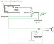
About the volume pot: I'm slightly confused as to the number of wires going to/from it - until your last point I was under the impression that the following (crude, but hopefully intelligible) drawing described the circuit accurately (Only one channel for simplicity, PSUs are not shown, but are assumed to be grounded to star ground. Also, the power amp has two connections to star ground because there's a ground loop breaker in between internally):

However, in your last post you said
And one last question before I can (hopefully) stop bothering you and get to work: Would you advise that I keep using shielded wire to carry the small signals to the pot or is that pointless? Getting rid of the shields would make the wiring a lot prettier and easier (especially since the shielding adds a lot of bulk to the wires), but I'm not sure if they actually do help. Given that the wires won't be coming from the same place anymore and that signals won't be all transmitted in paired wires, shielding seems a bit awkward...
Just to clear this up, the "P-ground" on the amp boards is meant to go to PSU ground - I would just connect both the input ground as well as the PSU ground point on the amp boards to star ground, did I understand that correctly?
About the volume pot: I'm slightly confused as to the number of wires going to/from it - until your last point I was under the impression that the following (crude, but hopefully intelligible) drawing described the circuit accurately (Only one channel for simplicity, PSUs are not shown, but are assumed to be grounded to star ground. Also, the power amp has two connections to star ground because there's a ground loop breaker in between internally):
However, in your last post you said
Assuming you're using the braids/shields as return conductors and not as EMI shields, why would they need to be connected to star ground and/or the volume pot? Isn't the volume pot's connection to star ground along with the preamp and power amp being grounded to star ground enough, so that return conductors wouldn't be needed as the return path is already given by the volume pot's connection to star ground?remember to not connect the signal wires braids to the ground point in the board/s. You should connect them on the volume pot side and to the star.
(...)
I use 1 single 2 mm2 (14AWG) to ground the pot body, both ground pins, and the corresponding input and output wires braids to the star.
And one last question before I can (hopefully) stop bothering you and get to work: Would you advise that I keep using shielded wire to carry the small signals to the pot or is that pointless? Getting rid of the shields would make the wiring a lot prettier and easier (especially since the shielding adds a lot of bulk to the wires), but I'm not sure if they actually do help. Given that the wires won't be coming from the same place anymore and that signals won't be all transmitted in paired wires, shielding seems a bit awkward...
Last edited:
Alright, thank you for your advice!
Just to clear this up, the "P-ground" on the amp boards is meant to go to PSU ground - I would just connect both the input ground as well as the PSU ground point on the amp boards to star ground, did I understand that correctly?
Then yes, route both connections to the star ground. Use separate wires for this.
About the volume pot: I'm slightly confused as to the number of wires going to/from it - until your last point I was under the impression that the following (crude, but hopefully intelligible) drawing described the circuit accurately (Only one channel for simplicity, PSUs are not shown, but are assumed to be grounded to star ground. Also, the power amp has two connections to star ground because there's a ground loop breaker in between internally):
However, in your last post you said
Assuming you're using the braids/shields as return conductors and not as EMI shields, why would they need to be connected to star ground and/or the volume pot? Isn't the volume pot's connection to star ground along with the preamp and power amp being grounded to star ground enough, so that return conductors wouldn't be needed as the return path is already given by the volume pot's connection to star ground?
In this case, and if you keep using shielded wires (braided) the braid won't shield from anything if it's not grounded. That's why I recommend to ground them at the pot and to the star.
You're right about the signal path ground is already stablished. This is just for shielding purposes.
And one last question before I can (hopefully) stop bothering you and get to work: Would you advise that I keep using shielded wire to carry the small signals to the pot or is that pointless? Getting rid of the shields would make the wiring a lot prettier and easier (especially since the shielding adds a lot of bulk to the wires), but I'm not sure if they actually do help. Given that the wires won't be coming from the same place anymore and that signals won't be all transmitted in paired wires, shielding seems a bit awkward...
Braided wires indeed take a lot of space but you will get good results with them if you use a good quality one. You can also use normal wires in twisted pairs as recommended in posts above. The same principle applies, as ground the negative wire just on the pot.
All ground paths have to behave like dead end streets. If you connect a ground wire to a place already grounded, a ground loop WILL develop.
Last edited:
- Status
- Not open for further replies.
- Home
- Amplifiers
- Solid State
- Grounding issues with P101, RK27 and The Wire