I'm running a sim with 4200u big caps for thd plotting. This takes quite some time to run, so it'll come later when ready.
It might be good to run it at 4100u as well, as it could also be the better value, although I don't think that size cap could be found.
I wish I could plot thd against a stepped cap value, but I couldn't figure out how to do that. A curve would speak better than raw numbers.
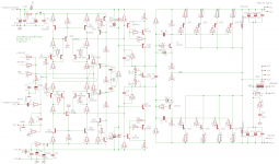
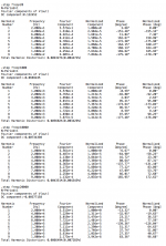
I'm running that thd sim with the thd analyzer, with the restored supplies on the front end, although I left out the serial res on them (doesn't change anything really).
And I kept the input cap shorted, so we're more looking at the big caps impact.
It might be good to run it at 4100u as well, as it could also be the better value, although I don't think that size cap could be found.
I wish I could plot thd against a stepped cap value, but I couldn't figure out how to do that. A curve would speak better than raw numbers.
I'm running that thd sim with the thd analyzer, with the restored supplies on the front end, although I left out the serial res on them (doesn't change anything really).
And I kept the input cap shorted, so we're more looking at the big caps impact.
as the 15032/33 are ground referenced, cascoding is relatively easy with just a small swing penalty..
the other advantage is that you can select a low voltage transistor with higher Ft and linear beta so you can place the dominant pole more or less where you want (Ft/beta)
The sweet spot for the big filter caps value looks to be somewhere between 4100 and 4200u. Not very much difference between those values, perhaps a tiny bit better with 4100u. But 4100u is unlikely to be a workable value.
Perhaps splitting the total value between more smaller caps might be a good thing, with low esr caps, or maybe have a large one and more smaller ones together, some combination...
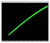
Our thd isn't bad with the input cap removed, at least at the low end it's better.
The cascoding of the drivers perhaps are something to explore to lower thd a little more, if any. Although that won't do anything for noise.
Perhaps splitting the total value between more smaller caps might be a good thing, with low esr caps, or maybe have a large one and more smaller ones together, some combination...
Our thd isn't bad with the input cap removed, at least at the low end it's better.
The cascoding of the drivers perhaps are something to explore to lower thd a little more, if any. Although that won't do anything for noise.
Attachments
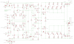
I had thought we might be looking at how changing the Current Mirror resistors affected noise. I suspect using 220/2.2k would be interesting. Is that still on the agenda?
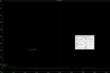
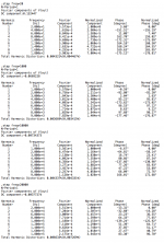
Noise is indeed slightly lower with the 220/2k2 values in the CM, and thd perhaps a tiny bit lower.
We gain in the order of 0.3db of SNR with those values, so I guess it's better that way. The gain isn't a lot though.
I tried making this comparison as meaningful as possible. Since it changes the operating point when changing those CM res values, I tried matching the rail offsets, although the vas bias is slightly higher with 220/2k2 than with 100/10k.
I did this leaving the big filter caps at 4700u and the input cap left in as well.
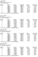
We have a little over 89db of SNR apparently. Not a stellar performance, but could be worse. The thd performance isn't bad. Remains to be seen how a real build would be.
Attachments


The sweet spot for the big filter caps value looks to be somewhere between 4100 and 4200u. Not very much difference between those values, perhaps a tiny bit better with 4100u. But 4100u is unlikely to be a workable value.
And now a practical question arises: As even nowadays' electrolytics use to have tolerances of +50 and -20%, respectively, are we still willing to adjust the capacity that a sim tells us to be the optimum, individually for each build?
I'm rather curious on the reason of this sweet spot 😕.
Best regards and a happy new year to all of you!
And now a practical question arises: As even nowadays' electrolytics use to have tolerances of +50 and -20%, respectively, are we still willing to adjust the capacity that a sim tells us to be the optimum, individually for each build?
Well, this is where the caps could be included in the part selection and matching work, to make sure they are as suitable as possible. A digital meter that can measure capacitance doesn't cost much and it's nothing much to do the extra work to actually test out those caps as well as the other parts before building.
Especially knowing how loose the tolerances are on those parts, why not spend a tiny bit more time on testing them? I surely would. I have a meter for it, and it didn't cost much. Actually there are $5 digital devices on ebay that can measure far more than just capacitance, and they are fairly accurate too.
When you're a hobbyist and you want to make your own amps, to be the best you can make, you should be open to do what's necessary.
I'm rather curious on the reason of this sweet spot 😕.
Me too!
I am very curious about that and how the value is calculated.
Intuitively I would've thought the bigger the better, and I was quite surprised to find out it's actually not the case.
If someone could share some insight into this, I'm eager to learn more about this.
And I was just thinking, testing the caps for their values is good, but it doesn't have to stop there. Why be lazy when building something like this, if you love what you do and make all attempts to make it the best possible?
While measuring the caps values, they can also be matched, so both sides get the same thing, and the optimal values.
If I'm making my own amp, I want it as good as possible and as close as possible to what theory (and sim) says it should be. And this is where our builds are more likely to outperform even the best commercial builds, which are chain manufactured and certainly no efforts on part matching or testing is put into it.
Good idea, noted for later on. This output stage with gain is cantankerous and tends to oscillate, so changes of anything have great risk. Actually slower devices worked better for the outputs, so the output stage behavior is counterintuitive. What better low voltage, high current devices would you suggest?as the 15032/33 are ground referenced, cascoding is relatively easy with just a small swing penalty..
We're walking through the input section, focusing at present on the effects of emitter resistor values on noise from the EF current mirror. I'm hoping we converge on a solution, and move to the next logical step.
I'm thinking the LTP current sources might be next, if Spookydd concurs. The strawman solution we have now is frozen so we can see the effects of changes elsewhere, particularly in the LTP current mirrors. I am not sold on this oddball current source. I suggested it out of curiosity and it stuck. It's cute, but not a regulated current source.
Attached are 3 alternatives. I suspect only the 20khz runs will reveal much.
Attachments
indeed, the output stage has an open loop current gain of approx 50dB. adding a cascode increases this to 70dB plus more phase rotation. this part of the circuit is extremely sensitive to transistor current gains. a lower gain bottom transistor for the cascode could be selected, like the ZXTN25020DFH but still more compensation is needed with a total Ft of approx 7Mhz with 45 degree phase margin.
I'm thinking the LTP current sources might be next, if Spookydd concurs. The strawman solution we have now is frozen so we can see the effects of changes elsewhere, particularly in the LTP current mirrors. I am not sold on this oddball current source. I suggested it out of curiosity and it stuck. It's cute, but not a regulated current source.
Attached are 3 alternatives. I suspect only the 20khz runs will reveal much.
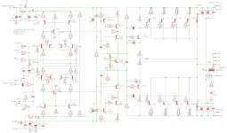
So far, the non-oddball solutions haven't really been that much better than the oddball one.
To make things a little more understandable, I'll post those 3 options separately.
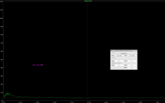
So far, comparing the resistor only solution to the active ones, doesn't change things very much. The noise is a tiny bit lower, and thd a very tiny bit higher, but nothing significant.
That resistor only solution isn't bad really, and it does bring the part count down. It's hardly worse than any active solutions we've tried.
Attachments
With those current sources, we have a little more noise than with the resistor only option, and thd is also roughly the same.
Attachments

Cascoding the sources doesn't seem to bring much really, if any.
Perhaps there are other behaviors that may benefit from this, but not noise and thd really.
Perhaps there are other behaviors that may benefit from this, but not noise and thd really.
Attachments
Variations on the current source yielded surprisingly little improvement. Hmm... not what I expected.
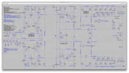
OK, what does cascoding the LTP do? Two variations below. 20khz is the most interesting run.
OK, what does cascoding the LTP do? Two variations below. 20khz is the most interesting run.
Attachments

OK, what does cascoding the LTP do? Two variations below. 20khz is the most interesting run.
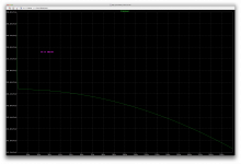
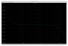
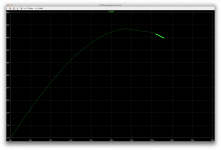
The first version introduces hf oscillations. The operating point takes a little while to be found, the voltage on the upper ltp output looks quite odd, especially since the lower one looks more normal.
The period of the oscillations seems to be around 800ns (1.25mhz?).
When I saw the simulation having a real hard time happening, I eliminated the delay cycles to see what was happening right away, and I took a snapshot to take a look. I didn't let it run all the way, it would take a very long time and there is no point in seeing the rest to realize what's happening.
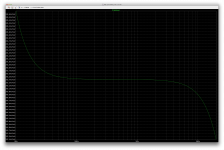
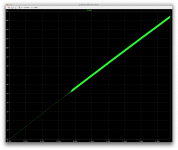
Take a look at the plot, this is the start of it, only the rising slope from the very first sine cycle. Very different kind of oscillation compared to what we've had in the early versions.
Attachments

OK, what does cascoding the LTP do? Two variations below. 20khz is the most interesting run.
This second version also has some issues.
I haven't tried a transient on it, as the operating point has a problem.
I takes a while to find the op and the rail centering is way off.
This one requires something more to fix those extra pairs bases I think.
Attachments

Spookydd said:
The period of the oscillations seems to be around 800ns (1.25mhz?).
...
Take a look at the plot, this is the start of it, only the rising slope from the very first sine cycle. Very different kind of oscillation compared to what we've had in the early versions.
I say: Two things happening. The current mirrors are disturbed, and the cascode may be oscillating. I have redefined the operating point for the cascode, roughly. I have added a base stopper as well.
Attachments
Spookydd said: This second version also has some issues.
I haven't tried a transient on it, as the operating point has a problem.
I takes a while to find the op and the rail centering is way off.
This one requires something more to fix those extra pairs bases I think.
I say: I modified the bias for the second version, did not add base stopper. The bias may be off by a diode drop and we may need base stoppers.
Attachments

I have redefined the operating point for the cascode, roughly. I have added a base stopper as well.
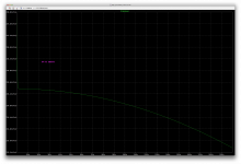
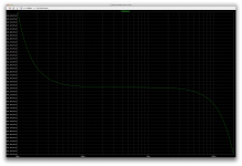
The operating point is found much better. The rail centering looks fine.
But oscillation still starts fairly quickly.
I see a discrepancy of nearly 900mV between the ltp output voltages. More than a slight imbalance it seems, but the rest looks fairly balanced.
Attachments
I modified the bias for the second version, did not add base stopper. The bias may be off by a diode drop and we may need base stoppers.
Better, the op is found better, but we have oscillations starting, and it kind of looks like the oscillations are happening after clipping, but the level is too low for clipping to occur, so something else is going on.
Attachments
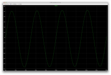
Just to make sure, I reduced a bit the input level to 1.3V.
The oscillations stop, so it was indeed at clipping that oscillations started, but it clips early, and that's not happening at the output stage.
So we've clipping early and at the input stages, and that's where the oscillations happen.
I guess this extra pair at the ltp eats up a little too much headroom, which makes the clipping happen there first.
Attachments
- Status
- Not open for further replies.
- Home
- Amplifiers
- Solid State
- grounded collector amp