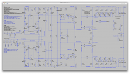
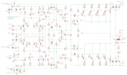
I reviewed the performance of our latest version, with zener CS, against an earlier version using mirror current sources. Actually, the mirror was better. So I refined it a bit to have a more constant current. This is an unconventional use of the mirror, but I'm keeping an open mind depending on performance.
You missed updating the cap value on the low negative rail.
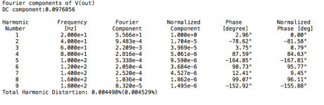
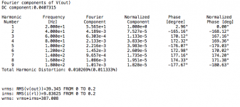
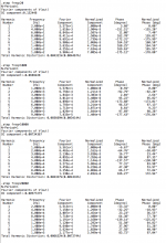
Anyway, the input filter change has increased the sensitivity a little, so we need a little less input level. I put 1.26V, as it looks like 1,27V brings it to the onset of clipping at the neg rail (a little imbalance, it starts clipping there first).
Noise has worsened a little, and thd is better in the pass band but not as good at each extremity. Especially it got worse at the low end.
Perhaps only due to the different input filter and not the current source changes.
Fact is, I don't know where the increase in noise really comes from, but I suspect not from the input filter. That current source topo may be noisier than the previous one. But I may be wrong though, the thd going up at the very low end has to be from that input filter.
It wastes much less input level, but seems noisier. Too bad. But maybe something can be done about it.
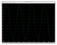
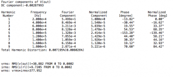
Just for kicks, I'll run an FFT with a higher resolution...
Attachments

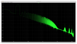
I need to run more fft plots trying other window functions, to see if the noise floor can be lower.
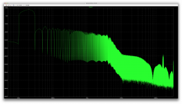
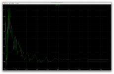
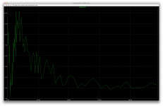
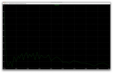
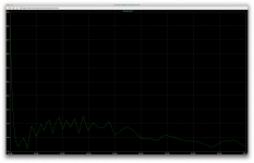
This plot shows a high noise floor, and we can't even really see the harmonics.
This plot shows a high noise floor, and we can't even really see the harmonics.
Attachments

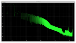
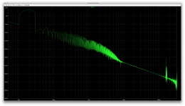
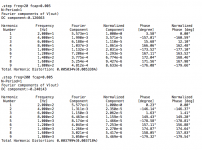
The hann window function may not be the optimal choice for ftt, but it shows the harmonics and we have a high noise floor.
We can see we have more 3rd harmonics than 2nd. The subsequent harmonics aren't dropping fast in level after that though.
I need to find a more appropriate window function to use.
Perhaps I'm running it at too high resolution as well...
We can see we have more 3rd harmonics than 2nd. The subsequent harmonics aren't dropping fast in level after that though.
I need to find a more appropriate window function to use.
Perhaps I'm running it at too high resolution as well...
Attachments
-
 Screen Shot 2016-12-22 at 8.53.03 PM.png537.3 KB · Views: 53
 -
 Screen Shot 2016-12-22 at 8.52.09 PM.png46.9 KB · Views: 65
 -
 Screen Shot 2016-12-22 at 8.51.13 PM.png503.4 KB · Views: 64
 -
 Screen Shot 2016-12-22 at 8.48.50 PM.png47.3 KB · Views: 68
 -
 Screen Shot 2016-12-22 at 8.45.09 PM.png431.5 KB · Views: 60

I think some advice from fft gurus would be helpful sorting this out.
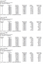
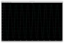
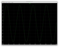
I have been skipping the first bunch of cycles in all measurements because the amp needs a little time to settle and it clips at the top on the first few cycles.
To make sure those clipped cycles are all ignored, I skipped the first 10, and only looked at the next 4 (on sine waves).
Earlier I used the hann window on the fft plot, and now the blackman, which seemed to have the favor of more people. And I tried using 64k and 131k data points.
I figure the ugly result with 64k points indicates that 131k would be a better choice, and the odd thing is that "looking" at more cycles improves the thd figure.
This set of data here was done at 20hz, and I saw the thd figure drop a bunch by going from 4 to 10 cycles analyzed. And not by a small amount, the drop was by more than half.
I don't understand how the thd would get lower when looking at more cycles.
Those figures go way up if we start looking at earlier cycles (skipping fewer), and it looks real bad if skipping nothing, which looks obvious because the first several cycles are clipped at the top.
One other thing is that the noise floor being high may just be due to the fact that the cycles being looked at aren't starting at a zero crossing.
Not certain this is the real issue, but it kind of makes sense.
I know our noise is a bit high, but really not that much, and nothing to put the floor at some -30 or -40db
That noise floor should be much lower than that.
How can we decide how many cycles to look at for fft? Since the resulting figures change depending on how many cycles we look at, how can we know what is right?
Attachments
Let's change back the input network. We need to have comparable results. So I restored the 14.3k input resistor.
The 20 hz distortion makes no sense. I'm wondering if the filters I put on the CS are causing it. If you can cut them, make one run at 20 hz, we'll see.
The 20 hz distortion makes no sense. I'm wondering if the filters I put on the CS are causing it. If you can cut them, make one run at 20 hz, we'll see.
Attachments
Let's change back the input network. We need to have comparable results. So I restored the 14.3k input resistor.
The 20 hz distortion makes no sense. I'm wondering if the filters I put on the CS are causing it. If you can cut them, make one run at 20 hz, we'll see.
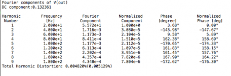
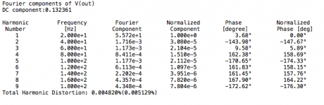
Clearly it's strictly the input filter and the caps on the current source have no impact whatsoever.
The first thd result is with the caps, the second without, and they're identical.
And the floating rails are much better balanced with this input scheme.
Too bad it's more wasteful of input signal, but it works better, has lower noise and lower thd.
Attachments

Clearly it's strictly the input filter .... the caps on the current source have no impact whatsoever. .. the floating rails are much better balanced with this input scheme. Too bad it's more wasteful of input signal, but it works better, has lower noise and lower thd.
Regarding the input scheme, all I did was make the input resistance equal on both inverting and non inverting sides. 14.3k is the proper value. I hoped increasing the input resistor to 33k would reduce low frequency distortion, but instead it caused a slight imbalance of input currents which increased distortion broadband. Bad idea.
Later on we can move it to the other side of the 1k, reduce it to 13.3k and the input currents still will balance, but there will be no signal waste. But so we can compare like to like, leave it for now.
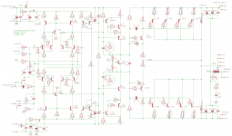
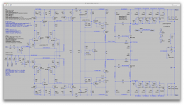
Depending on your runs with the corrected input value, I'm trying to decide on the best CS (between zener and mirror). There was a run with the simpler mirror CS that seemed best. Was that with the EF mirror on the LTP as in Post 395, or basic mirror as in post 389? I'm trying to recreate whatever gave the best run, and I'm confused because we both made changes and I lost track of what mirror was used on the best run. I think it was like your 395, attached.
Attachments
Later on we can move it to the other side of the 1k, reduce it to 13.3k and the input currents still will balance, but there will be no signal waste. But so we can compare like to like, leave it for now.
Ok, sounds good.
Depending on your runs with the corrected input value, I'm trying to decide on the best CS (between zener and mirror). There was a run with the simpler mirror CS that seemed best. Was that with the EF mirror on the LTP as in Post 395, or basic mirror as in post 389? I'm trying to recreate whatever gave the best run, and I'm confused because we both made changes and I lost track of what mirror was used on the best run. I think it was like your 395, attached.
We've gone through so many incarnations, it is indeed hard to keep track.
Perhaps we should do both schemes and compare.
Spookydd said: We've gone through so many incarnations, it is indeed hard to keep track. Perhaps we should do both schemes and compare.
I say: Yes, many incarnations, and syncing our efforts has been a challenge. Document control is an age old problem in engineering, particularly for teams spread worldwide. If I had Spice competence, I could do some of these little optimizations myself and speed the cycle. But in working together there has been a useful sharing of ideas that has obviously helped.
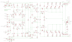
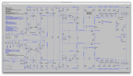
By the way, I just noticed that my last schematic is missing the 180k feedback resistors on the VAS, my mistake. So the attached schematic corrects that omission.
I say: Yes, many incarnations, and syncing our efforts has been a challenge. Document control is an age old problem in engineering, particularly for teams spread worldwide. If I had Spice competence, I could do some of these little optimizations myself and speed the cycle. But in working together there has been a useful sharing of ideas that has obviously helped.
By the way, I just noticed that my last schematic is missing the 180k feedback resistors on the VAS, my mistake. So the attached schematic corrects that omission.
Attachments
Sorry for the delayed work. I've been dealing with things lately that put a damper on this. From a car breakdown on xmas eve (not fun), to miscellaneous errands and a cold on top of that, it's been a little hectic lately.
Anyway, I hope I didn't miss on some value changes or whatever.
Here's what we have on this latest.
I doubt we'll do much better on thd, and probably on noise as well. And the slew rate remains basically what we've had recently at about 23V/us.
Seems not bad to me anyway. I'm not sure we can expect anything much better in all respects. This is a nice P.A amp as is.
Attachments
-
 Screen Shot 2016-12-29 at 3.00.07 PM.png157.4 KB · Views: 129
 -
 Screen Shot 2016-12-29 at 3.00.50 PM.png156.5 KB · Views: 133
 -
 Screen Shot 2016-12-29 at 2.58.33 PM.png254.9 KB · Views: 145
 -
 Screen Shot 2016-12-29 at 2.57.12 PM.png154.6 KB · Views: 162
 -
 Screen Shot 2016-12-29 at 2.57.32 PM.png719 KB · Views: 174
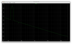
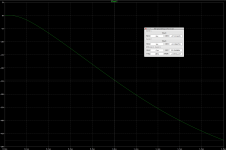
Here is something interesting about the thd profile.
When running a sim at just one frequency and look at the thd result, we don't get a full picture of it.
Looking at a curve shows much more.
Now I'm wondering about what's going on at the low end. I had no idea how the thd was rising when edging towards the low end, only that it was rising rather sharply.
Perhaps we can do something about that. Or at least push it further down below audibility, if not minimize it.
Attachments

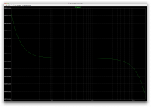
To look at it much closer, I ran the sim only on the low end, and at a much higher resolution. So many data points, it took a very long time to run.
Zooming in gives a little more of an idea, but why does it go up and down so much?
Anyway, we can see mostly where the rising thd is happening.
Zooming in gives a little more of an idea, but why does it go up and down so much?
Anyway, we can see mostly where the rising thd is happening.
Attachments
Rising distortion at very low frequencies is likely an artifact of some capacitor in the signal chain. Likely candidates are the input capacitor, the output reservoir caps, and resistance or of the RC filter on front end power. This can be localized.
First, use no input capacitor. I doubt an amp without input cap is practical in general, but it would prove a point. This is solely to isolate the source of the LF distortion. If that points mainly to the input capacitor/resistor, we can increase the size of those components somewhat, but there are practical limits.
Second, use an ideal power supply for the front end. This would again isolate the source. If needed we can supply better regulated power to the LTP and CS, using a separate regulator or a capacitance multiplier.
Third, make the reservoir capacitors somewhat larger. This has been explored a bit already and a sweet spot found, but we might look at it again.
I had thought we might be looking at how changing the Current Mirror resistors affected noise. I suspect using 220/2.2k would be interesting. Is that still on the agenda?
Rising distortion at very low frequencies is likely an artifact of some capacitor in the signal chain. Likely candidates are the input capacitor, the output reservoir caps, and resistance or of the RC filter on front end power. This can be localized.
I shorted it and ran a thd sim sweep again.
It does make a difference, but there is always a sharp rise at the low end, although much better without the cap.
First, use no input capacitor. I doubt an amp without input cap is practical in general, but it would prove a point. This is solely to isolate the source of the LF distortion. If that points mainly to the input capacitor/resistor, we can increase the size of those components somewhat, but there are practical limits.
I have been wondering if adding a smaller sized, perhaps a 1u or so, in parallel with the larger sized one, would improve things. Maybe the mix of 2 types of caps might help, and the difference in size would have their influence differ with the frequency ranges...
Second, use an ideal power supply for the front end. This would again isolate the source. If needed we can supply better regulated power to the LTP and CS, using a separate regulator or a capacitance multiplier.
Our supply is rather close to ideal, even with the added serial resistance.
I will try removing the serial resistance and separating the vas supply from the ltp and give the ltp its own. This should show if perhaps any disturbance from the vas affects the ltp. But it's doubtful there is much going on there, with such idealized supplies to begin with.
In a real build, that's an other story of course, and a better filtered and stabilized supply should definitely make a difference.
Third, make the reservoir capacitors somewhat larger. This has been explored a bit already and a sweet spot found, but we might look at it again.
That's one more avenue to explore. My previous experiments in that area did reveal something. It's worth looking into it some more. I it might be interesting to know why there is a sweet spot, where it comes from...
I had thought we might be looking at how changing the Current Mirror resistors affected noise. I suspect using 220/2.2k would be interesting. Is that still on the agenda?
Sure. We'll look at that too. Let's do some sims on those things for the thd and we'll look again at noise next. If we can find a way to improve the noise, that would be nice.
Attachments
Seems like idealizing the supplies doesn't really make any difference.
The thd profile looks basically identical with the perfect supplies, although this is likely to be different in a real build, where the supplies quality would count more.
We have a few more things to explore...
The thd profile looks basically identical with the perfect supplies, although this is likely to be different in a real build, where the supplies quality would count more.
We have a few more things to explore...
Attachments

why not cascode the 15032 and 15033 transistors. the voltage amplification needs to be very linear..
why not cascode the 15032 and 15033 transistors. the voltage amplification needs to be very linear..
We haven't been tweaking the power stages for some time now, as it's been stable as is. But perhaps that's something to explore, at least for lowering thd a little, because this won't affect noise.
I don't know how much thd comes from the power stages, but I suspect most of it comes from the front end and not really the power stages, although more linearity in those power stages might help better the thd a little. Not sure if this is going to make a large enough difference at this point. Maybe.
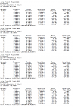
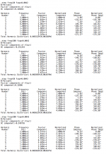
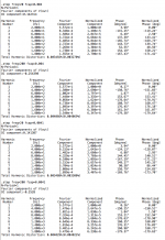
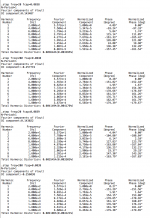
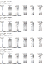
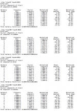
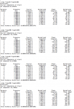
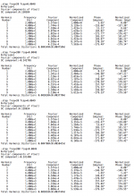
I tried stepping through values from 3000u to 5000u in 100u increments for the large filter caps, and this at frequencies of 20, 1k, 10k and 20k, and as I noticed before, those big caps values have no effect above 1khz, so since the data set put out is rather large, I tried stepping with frequencies of 20, 200, 500 and 1k, and it's too much data to post here practically.
Since the effect is so small at some 500-1khz, I also ignored that and reduced the data set by doing only 20 and 200, which is still a little much to post here but I will post 2 more shots on the next post, so we can have all that data.
The sweet spot seems to be near 4200u.
I will run a full thd sweep with that value, to see the profile...
Attachments
-
 Screen Shot 2017-01-01 at 12.25.21 PM.png154.9 KB · Views: 57
 -
 Screen Shot 2017-01-01 at 12.24.56 PM.png154.5 KB · Views: 58
 -
 Screen Shot 2017-01-01 at 12.24.40 PM.png155.6 KB · Views: 66
 -
 Screen Shot 2017-01-01 at 12.24.19 PM.png154.1 KB · Views: 62
 -
 Screen Shot 2017-01-01 at 12.23.50 PM.png153.3 KB · Views: 62
 -
 Screen Shot 2017-01-01 at 12.23.25 PM.png156.6 KB · Views: 53
 -
 Screen Shot 2017-01-01 at 12.23.02 PM.png153.2 KB · Views: 66
 -
 Screen Shot 2017-01-01 at 12.22.39 PM.png152.5 KB · Views: 65
 -
 Screen Shot 2017-01-01 at 12.22.15 PM.png153.1 KB · Views: 65
 -
 Screen Shot 2017-01-01 at 11.56.51 AM.png720.2 KB · Views: 65
- Status
- Not open for further replies.
- Home
- Amplifiers
- Solid State
- grounded collector amp