This is excellent. You are showing me a 1v offset at idle. I'm amazed it is that huge, but there you have it. I can deal with it. It all traces back to the input, and can be adjusted out there. I suspect the op amp should go back in, but I will tweak this basic design a little more.
I think opamps can cause stability issues. I prefer discrete. It has to be just right for the opamps to not cause troubles.
I will up the reference voltages for the input to ~10v and make them precision, and adjustable. Easy peasy. We can null any offset right there.
You must mean the zeners at the head of the input stage... From 6.2 to 10v then.
I know you took out the resistors I had between grounds for valid reasons, but you do realize I intended to star ground at the Power supply ground?
Of course, but like I said, in a sim, they really don't do much. The simulations don't really get quite that deep to show much effect from those. And we really can't get any parasitic interference coming in, from a nearby microwave or whatever...
For simulation, fine, out, but I obsess about ground loop hum and noise, so I do split ground on card.
Sure, absolutely, and this should be done in the real thing of course, but in a sim, there isn't much point doing so.
Same thing for the muting stuff, unless we want to further explore its function, at first to get the amp done right, we can omit that.
Later when the amp performs real well, then we can tackle those extras.
Updated GroundHog with offset null. Many issues handled, but I will add the op amp back for comparison later.
Ok, I don't think I have a decent model for the lm317 and not sure about any regulators anyway, but we don't need to simulate it with that detail yet. We can just use voltage sources for now and test it.
I see quite a few value changes. Let's double check my work to make sure I didn't leave any out.
I noticed it behaved again more like a comparator with a signal of more than 3v, and small and distorted waveform below that. So I shorted the input to see what's going on with the operating point.
I see the bias currents in the drivers are rather dissimilar, especially since the other currents earlier in the stages look much better balanced.
For the input transistors, I was going to suggest the lower noise BC550/560C, with very high gain, it should work nicely, and their max Vce0 should not be an issue there, with such low rails. But the 546/556B should do fine as well.
We can simulate later with actual lm317 models, but for now this should work to allow us to fix it.
I tried lowering the res value for the bias trimmer, but as you can see on the screenshot, it's still not quite working to bias this right.
I think the bias current in the drivers seem rather high.
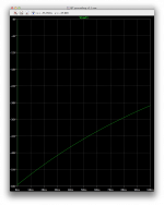
I put it back to 91 at the trimmer, and the plot was made from that. Look at what happens with the rails and output. (input is shorted)
I wanted to have data flags showing currents, but it's not easy on the mac, because ltspice is crippled to not allow doing this. So I have to either load the sim in a windoze based ltspice to make the flags, or edit them by hands externally in a text editor. It's tricky and time consuming, but I used a text editor. So we have some currents to show us more of what's going on at operating point.
Curious that with the input shorted that way we don't have 0v at the bases of the input stage...
The offset at the output looks very low as is, so we don't really need to correct it by tweaking a voltage source on the input stage references.
Attachments

Hi Spookydd,
What is missing in your model - is the center tap of the floating power supply.
Yes, it's floating. But it's got a positive rail, negative rail and central tap, connected to the amplifier's output before the inductor (the point you take the NFB signal from). See the QSC EX schematic fragment.
I explained the way this OPS is working in some other thread - I can't find those posts right now.
Cheers,
Valery
Attachments

What is missing in your model - is the center tap of the floating power supply.
There is no center tap used in the qsc1700 and also the 1200 for which I am posting a schematic here.
So it's done in different ways on different models.
I'd like to try making a simulation of that one shown on that last posted schematic, but it's incomplete and although I have many qsc service manuals, I don't have that one. Could you share that manual?
Yes, it's floating. But it's got a positive rail, negative rail and central tap, connected to the amplifier's output before the inductor (the point you take the NFB signal from).
Since the 1700 and 1200 don't use it, it should work.
See the QSC EX schematic fragment.
This is really a fragment, and I'd like to draw up a sim for it, so I'll need a more complete schematic. Which model is shown on that schematic?
Attachments
Ok, I don't think I have a decent model for the lm317 and not sure about any regulators anyway, but we don't need to simulate it with that detail yet. We can just use voltage sources for now and test it.
I see quite a few value changes. Let's double check my work to make sure I didn't leave any out.
I noticed it behaved again more like a comparator with a signal of more than 3v, and small and distorted waveform below that. So I shorted the input to see what's going on with the operating point.
I see the bias currents in the drivers are rather dissimilar, especially since the other currents earlier in the stages look much better balanced.
For the input transistors, I was going to suggest the lower noise BC550/560C, with very high gain, it should work nicely, and their max Vce0 should not be an issue there, with such low rails. But the 546/556B should do fine as well.
We can simulate later with actual lm317 models, but for now this should work to allow us to fix it.
I tried lowering the res value for the bias trimmer, but as you can see on the screenshot, it's still not quite working to bias this right.
I think the bias current in the drivers seem rather high.
I put it back to 91 at the trimmer, and the plot was made from that. Look at what happens with the rails and output. (input is shorted)
I wanted to have data flags showing currents, but it's not easy on the mac, because ltspice is crippled to not allow doing this. So I have to either load the sim in a windoze based ltspice to make the flags, or edit them by hands externally in a text editor. It's tricky and time consuming, but I used a text editor. So we have some currents to show us more of what's going on at operating point.
Curious that with the input shorted that way we don't have 0v at the bases of the input stage...
The offset at the output looks very low as is, so we don't really need to correct it by tweaking a voltage source on the input stage references.
Thank you, this is so illuminating. There is a problem with Vbias, it should be 2.2 Vbe. It's current starved. That accounts for the weak gain below 3v. Above that, the drivers slam full on so it acts like a comparator. Several component values need adjustment. I will repost.
Main rails ALWAYS have some reference - it will not work properly otherwise
EX series utilizes the same topology and same service manual for all models (800, 1250, 1600, 2500, 4000).
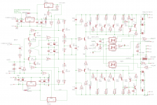
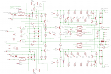
If you look at 1700 and 1200 schematic carefully (fragment from your file is attached here), you will see that +/-15V rails for the OpAmps are arranged by R20, R21 and Z1, Z2 (15V zeners). This is critically important - that's the way the "floating" main supply if referenced to ground - OpAmps do all the rest, balancing out DC at the output.
Same thing with MX series. 700 model is using the OpAmps' rails reference, 1000a, 1500a, 2000a - central tap at the output.
This thing will not work with the main supply totally isolated. It's either referenced through the OpAmps' rails, or through the center tap connected to the output. Draw a simplified schematic and see the way the currents flow - you will see it will not work with the main rails not referenced at all.
Cheers,
Valery
There is no center tap used in the qsc1700 and also the 1200 for which I am posting a schematic here.
So it's done in different ways on different models.
I'd like to try making a simulation of that one shown on that last posted schematic, but it's incomplete and although I have many qsc service manuals, I don't have that one. Could you share that manual?
Since the 1700 and 1200 don't use it, it should work.
This is really a fragment, and I'd like to draw up a sim for it, so I'll need a more complete schematic. Which model is shown on that schematic?
EX series utilizes the same topology and same service manual for all models (800, 1250, 1600, 2500, 4000).
If you look at 1700 and 1200 schematic carefully (fragment from your file is attached here), you will see that +/-15V rails for the OpAmps are arranged by R20, R21 and Z1, Z2 (15V zeners). This is critically important - that's the way the "floating" main supply if referenced to ground - OpAmps do all the rest, balancing out DC at the output.
Same thing with MX series. 700 model is using the OpAmps' rails reference, 1000a, 1500a, 2000a - central tap at the output.
This thing will not work with the main supply totally isolated. It's either referenced through the OpAmps' rails, or through the center tap connected to the output. Draw a simplified schematic and see the way the currents flow - you will see it will not work with the main rails not referenced at all.
Cheers,
Valery
Attachments
Thank you, this is so illuminating. There is a problem with Vbias, it should be 2.2 Vbe. It's current starved. That accounts for the weak gain below 3v. Above that, the drivers slam full on so it acts like a comparator. Several component values need adjustment. I will repost.
Simulating during the design process really helps to make things right before you build something and get surprised it doesn't behave like you planned it would.
Of course you can discover issues and fix them at the time of breadboarding, but the simulation should provide far more details than you would ever get from breadboarding a curcuit, plus the simulations allow doing all kinds of "what if" possibilities.
This concept of the grounded source is quite interesting. QSC does it in a different way than Crown, but it's mostly the same thing. Crown's grounded bridge isn't so easy to reproduce properly. Those guys know what they're doing.
The thing is, the QSC scheme can be bridged, but then that's it, while the Crown grounded bridge scheme allows bridging a bridge, which is a hell of a thing, with 4 power amps working together.
The grounded source has that big advantage of much easier and more efficient heatsinking, plus the simpler psu (not always), and it seems very robust and resilient against faults.
The grounded bridge can provide a huge power from much lower rails than any other topo, which allows putting out far more power than anything else with devices able to handle much lower voltages.
I find this very interesting. We have a thread on the grounded bridge using 2N3055, and it's amazing how much power we can get out of these puppies. Not to mention the simulations have shown we can get a really nice performance distortion wise even with the old venerable 3055.
One other thing, is that both QSC and Crown always make their amps using opamps, no discretes... But I'd like to see this happen with all discrete.
Actually our couple of designs on the grounded bridge thread are both all discrete, and one of them has a very nice performance that deserves a build.
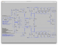
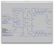
Updated GroundHog with offset null and changes.
Ok, I made an updated sim, and unless I missed something, the operating point seems much better now and the bias has become controllable.
See in the 1st screenshot, with the raw values for the bias trimmer, we hardly have any bias current in the outputs.
More in next posting.
Attachments
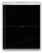
Now in this next screenshot, I adjusted the bias trimmer down to 80 and we have a reasonable bias current through the outputs. Look at the current in R23 as labeled.
This should be about right, unless we need to increase that somewhat depending on crossover distortion later.
But one thing I wonder, isn't that bias current in the vas a little high?
I would think that should be perhaps about half of that, maybe even a little less.
This should be about right, unless we need to increase that somewhat depending on crossover distortion later.
But one thing I wonder, isn't that bias current in the vas a little high?
I would think that should be perhaps about half of that, maybe even a little less.
Attachments

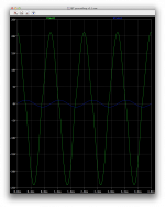
Now once the input short is removed and we do a transient with 1V at the input, we still get the comparator type behavior, so I reduced the input signal amplitude, several times, all the way down to what you see in the next screenshot (10mv), and look at what we get out.
Something is still not quite right, but this is coming together...
Something is still not quite right, but this is coming together...
Attachments
I changed the front end to try an op amp and add an auto zero. Rough early design, probably has design errors. I do like the simplicity and auto zero.
For that one, it's a different simulation. Let's get the first one going and we'll make one for this as well.
EX series utilizes the same topology and same service manual for all models (800, 1250, 1600, 2500, 4000).
Yes, I found that service manual, and I started to draw up a sim for the ex800, but as we can see in their schematic, quite a bit is obfuscated in blocks for the various protections, thermal management and more, which makes it impossible to draw up a sim with everything in it.
I can simplify, but many things will be missing.
And I see in that model they are using a vactrol based anti-clipping limiter, which I had not seen in the previous models I looked at.
This seems to have become a somewhat popular means to control the input level to prevent clipping.
If you look at 1700 and 1200 schematic carefully (fragment from your file is attached here), you will see that +/-15V rails for the OpAmps are arranged by R20, R21 and Z1, Z2 (15V zeners). This is critically important - that's the way the "floating" main supply if referenced to ground - OpAmps do all the rest, balancing out DC at the output.
And we can see clearly that the main psu rails aren't with a central tap, on those models, but ltspice doesn't manage to get this working.
Same thing with MX series. 700 model is using the OpAmps' rails reference, 1000a, 1500a, 2000a - central tap at the output.
I suspect it might work better that way in simulations. I'll have to try that, but so far there is so much obscured in the ex800 schematic, I'm not sure I can get enough of it to make it work.
This thing will not work with the main supply totally isolated. It's either referenced through the OpAmps' rails, or through the center tap connected to the output. Draw a simplified schematic and see the way the currents flow - you will see it will not work with the main rails not referenced at all.
You're probably right, ltspice has too much of a hard time with it when there is no obvious reference.
I'll try others, but one thing at a time, as I'm also trying out something else now.
And we can see clearly that the main psu rails aren't with a central tap, on those models, but ltspice doesn't manage to get this working.
As I mentioned - if there's no center tap, the key thing is inter-relation between the main "floating" rails and +/-15V front-end rails. In QSC models, not utilizing the center tap, that link is always there. Otherwise OPS will not work properly, even in theory, as you can see in your simulations so far.
LTSpice is just a comprehensive calculator. "Garbage" in -> "garbage" out 😉
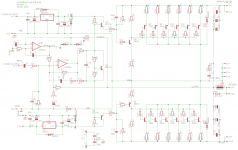
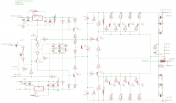
Here is an attempt at making this work.
I tried R14 and R41 in the vas at 100 ohms, then now 120, and the vas bias current is more in line with something ordinary, while the bias in the outputs is rather low and we can't decrease the value of the bias trimmer much lower than what you see on the current schematic, without causing serious distortion on the output.
We can see the output waveform does show distortion at the crossover.
I'm still seeing quite a bit of phase delay between input and output, but perhaps that's the "normal" phase shift induced.
There was no need to adjust the ref voltage on the input to correct any offset, as it's quite tiny.
Attachments
Here is an attempt at making this work.
I tried R14 and R41 in the vas at 100 ohms, then now 120, and the vas bias current is more in line with something ordinary, while the bias in the outputs is rather low and we can't decrease the value of the bias trimmer much lower than what you see on the current schematic, without causing serious distortion on the output.
We can see the output waveform does show distortion at the crossover.
I'm still seeing quite a bit of phase delay between input and output, but perhaps that's the "normal" phase shift induced.
There was no need to adjust the ref voltage on the input to correct any offset, as it's quite tiny.
Because this is a low voltage front end, dissipation is very low in the VAS transistors, so don't worry much about that. We need to get the Vbias up, to reduce crossover distortion. It looks like a lot of bias generator current is being shunted via the divider resistors, so rather than reducing the lower resistor, increase both. The real metric is the bias current in the output transistors, where I aim for 50ma per output roughly, not critical. We're close, but showing crossover, so that may need to be 100ma per.
The extreme comparator behavior must end. We can reduce the gain of the front end, by removing the complementary Darlington transistors, or adding local feedback, or both. I show both in the schematic below. If it is easy, I'd like to know the effect of each change independently. Try the local feedback via the 270k resistors alone. Try removing the complementary transistors in the first stage alone. Try both together. If you do only one, do the last.
There are stability risks with nested feedback so this is a critical analysis. It is so incredibly useful to have this modeling.
Attachments
The reason you're having trouble with this, and why qsc uses an op amp is because the output stage is inverting. The ground and speaker out are swapped, so it needs an inverting front end. Look at the qsc schematic, and see which pin the signal goes in, and which the feedback goes in.
The reason you're having trouble with this, and why qsc uses an op amp is because the output stage is inverting. The ground and speaker out are swapped, so it needs an inverting front end. Look at the qsc schematic, and see which pin the signal goes in, and which the feedback goes in.
You are correct. The negative feedback should be applied directly to the input node. A modified schematic follows.
Attachments
You are correct. The negative feedback should be applied directly to the input node. A modified schematic follows.
Hi Slowhands,
You have to take in account that if AC signal source at the input is low impedance (most of them are low enough), R1+R9 appear connected in parallel with R2. So the feedback ratio is very different from what you expected (overall gain is pretty much higher). Influence of R2 here is rather low in gain equation, assuming its high value, comparing to R1+R9.
Cheers,
Valery
- Status
- Not open for further replies.
- Home
- Amplifiers
- Solid State
- grounded collector amp