I added a 2 x 47k5 resistor divider rail to rail and the middle point to ground, but that still doesn't center it at rest.
The output is very well centered though.
(still the input grounded)
The opamp gives a big offset on its output, but that can only be due to the large voltage difference on its supply rails, the +v being normal at the 15v, but the -v is far from the intended -15v.
The output is very well centered though.
(still the input grounded)
The opamp gives a big offset on its output, but that can only be due to the large voltage difference on its supply rails, the +v being normal at the 15v, but the -v is far from the intended -15v.
Attachments
Try two sources with speaker connected on "centertap".
I tried it with F5T and it worked fine in LTSpice. I cant send any files thou, I'm at work.
Figge
Edit:
And PS-caps needs to be in there to.
I tried it with F5T and it worked fine in LTSpice. I cant send any files thou, I'm at work.
Figge
Edit:
And PS-caps needs to be in there to.
Last edited:
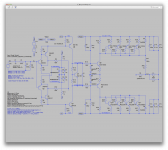
I tried this, which is basically as shown on the schematic from post #16, and of course that does "tame" the issue in ltspice, but then it's not the same topology.
The true floating grounded source topo as used in the qsc amps doesn't ties the speaker to a psu center tap. The power supply doesn't have a center tap and the speaker hot goes in the center tap of the filter cap bank, which isn't tied to a psu center tap.
This is really a tricky thing to model in spice. I would really like to make this work as they do it.
Have you added the appropriate parasitic elements / characteristics to the capacitors, especially the main PSU capacitors?
...
...
Which ones are those?
I didn't put any in my sim, but I don't see any in the qsc 1700 schematic either.
Maybe I missed them.
That could be what it needs to center properly...
Perhaps it might be good to have some kind of servo on those.
... I don't see this amp passing dc.
The filter caps being sizable makes the low cut off real close to 0hz, but not dc.
....
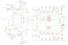
I mentioned three ways ground is established, but I think the dominant one is a resistor to ground at the center of the feedback divider. This is done in two different ways in the schematics posted. I was referring to the RAM schematic in the first post. They showed two equal 47.5k resistors between the floating power voltages, the midpoint being virtual AC ground. Later someone posted an actual QSC 1700 schematic, which has a single 16.5k 1/2w resistor to ground, in the center of the NFB divider. This change allowed easier bridging of the 1700 amp. In my QSC1400 early version, they use two resistors like the RAM, and I suspect the RAM design is based on the early QSC designs.
In all cases, there is no DC blocking cap to ground in the feedback divider. There can't be, because this is where ground is established. As a side effect the op amp offset voltage is multiplied at the output by the ratio of the feedback divider. No big deal in a PA amp, I guess. They could add a pot or servo to null it, but don't.
Yet another amp implementation to perhaps simulate?
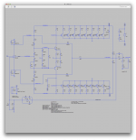
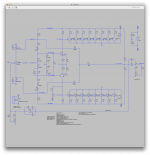
I have been doing a design similar to the others here. I wonder if it centers?
I have been doing a design similar to the others here. I wonder if it centers?
Attachments
Last edited:
A similar thread can be found here with what is IMHO a better way of doing things:
http://www.diyaudio.com/forums/solid-state/299418-common-emitter-ops.html
Might be worth a read...
http://www.diyaudio.com/forums/solid-state/299418-common-emitter-ops.html
Might be worth a read...
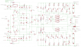
Slight Schematic Error
The schematic I posted earlier can't be edited nor deleted, but it had a goof. I was working mainly on the muting circuit and misconnected the output. So, here is a fix.I have been doing a design similar to the others here. I wonder if it centers?
Attachments
Have you added the appropriate parasitic elements / characteristics to the capacitors, especially the main PSU capacitors?
I tried increasing the series resistance of the voltage supply, but it didn't change anything.
I swapped the filter caps for others from the ltspice library. I picked a pair of 10mf from nichicon, so those should be modeled with all the necessary behaviors.
It didn't improve much tough.
Then I tried separating the opamp from the rest, to see how much it is responsible for that large offset.
And I can see it is largely responsible, but not only, because although the rails get much closer to balance, they're still much too far away from what's needed.
I'm posting a screenshot of it with those changes and with the resistor divider that I added on the voltage source.
The stuff close to ground like the drivers and the bias stuff are much better balanced, but the rails are still floating much too far away from center.
Attachments
I mentioned three ways ground is established, but I think the dominant one is a resistor to ground at the center of the feedback divider. This is done in two different ways in the schematics posted. I was referring to the RAM schematic in the first post.
Ok. That one is very similar to the qsc but not quite identical.
I tried to add a resistor divider to attempt to better balance the rails, but it's not enough.
They showed two equal 47.5k resistors between the floating power voltages, the midpoint being virtual AC ground.
I guess that's what I tried. Without success. So far.
Later someone posted an actual QSC 1700 schematic,
Me perhaps.
which has a single 16.5k 1/2w resistor to ground, in the center of the NFB divider. This change allowed easier bridging of the 1700 amp. In my QSC1400 early version, they use two resistors like the RAM, and I suspect the RAM design is based on the early QSC designs.
I saw that, and when not bridged, that resistor comes in parallel with the R/C from the feedback goind to ground, so it's kind of short circuiting the effect of that cap in series, and changes the feedback, and gain.
Then when it's in bridged mode, then what does the job of that resistor? No more direct ground link.
In all cases, there is no DC blocking cap to ground in the feedback divider. There can't be, because this is where ground is established.
Well at least this doesn't permit the amp to pass dc anyway, since the hot end of the speaker only goes to the center point between the filter caps. So even with the direct link to ground on the feedback, that amp still can't pass dc. Which is not a bad thing, as it's a designed-in speaker protection against dc, sort of, partly.
In case of a fault in the output stage, I guess the speakers are not too much in danger anyway. Once the big pop surge has passed through, the speakers should not see anything if a rail is brought down by shorted devices.
As a side effect the op amp offset voltage is multiplied at the output by the ratio of the feedback divider. No big deal in a PA amp, I guess. They could add a pot or servo to null it, but don't.
They probably don't worry much about that, since the amp can't pass dc.
Maybe once it's idling, the caps are blocking all dc and the speakers can't see any of it.
I have been doing a design similar to the others here. I wonder if it centers?
Interesting! And no opamp!
We'll have to try that out.
The schematic I posted earlier can't be edited nor deleted, but it had a goof. I was working mainly on the muting circuit and misconnected the output. So, here is a fix.
I had started using the first one to make up the sim and saw the bad output connection.
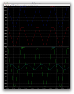
I finished drawing it up and although I did forget one connection when I tried it, it did look like it was working right out of the box. The connection that I forgot was the main feedback, and I had the input signal only at 1V (peak), so there wasn't a huge output power out, about 25V rms or so, and the signal looked fairly nice, visually.
I then noticed how low the gain was and pumped up the input signal to 10V, which pushed it was above clipping, and I looked at the output and both rails waveforms, which were nicely following each other, all the way.
I first tried with 50V rails, then figured I'd push that to 60V (120V total).
Then I did catch the missing feedback connection, and I noticed the signal would look worse that way, and even more triangular than sine.
Maybe I made a mistake somewhere, perhaps in resistor value or whatever.
It's a start. Let's see how this works.
Attachments
As you all noticed, I didn't include the regulators and stuff for the input stage's power supply, and the muting stuff. This doesn't need to be there at first to test the basic amp.
Plus I didn't bother separating the grounds with the low value resistors. I think for the purpose of simulating, this is pointless.
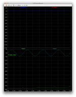
That said, I tried again with the removed feedback, because it works better that way. Look at the screenshots.
I do notice a phase shift, once the input and output signals are together, we can see this is obvious...
With 3V peak of input signal, and no feedback, we don't get a big gain and the signal still looks fairly nice.
Once I close the feedback loop though, things get dicy.
Plus I didn't bother separating the grounds with the low value resistors. I think for the purpose of simulating, this is pointless.
That said, I tried again with the removed feedback, because it works better that way. Look at the screenshots.
I do notice a phase shift, once the input and output signals are together, we can see this is obvious...
With 3V peak of input signal, and no feedback, we don't get a big gain and the signal still looks fairly nice.
Once I close the feedback loop though, things get dicy.
Attachments

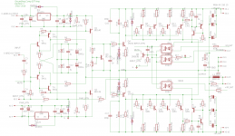
And when driving it hard beyond clipping, we can see it would clip gently, and we can also see that bias isn't right.
I tried adjusting the bias, but this doesn't really work. With R14 down below 10k or up to 20k, it still won't adjust the bias much.
I know, I just put a fixed resistor instead of a pot, but it turns out the same anyway, since adjusting a cursor on a pot or a value for the fixed resistor does the same thing.
I think having 2 diodes in the drivers' bases is too much and it drives the bias current way up, to over 400mA, and we can't bring it down with the bias adjustment.
Attachments
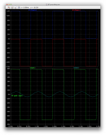
With the feedback loop closed, it's behaving oddly.
With 5V input, the rails get stuck at the -V end and there is only a mostly dc signal all the way down to -V on the output.
And curiously, with 6V instead of 5, we get a mostly square wave out, looking like a huge gain amp with a hard driving signal that pushed it very far above clipping.
I don't see how the gain could be way low without feedback and then applying feedback would make the gain so huge.
It works more like a comparator this way.
Attachments
With the feedback loop closed, it's behaving oddly.
With 5V input, the rails get stuck at the -V end and there is only a mostly dc signal all the way down to -V on the output.
And curiously, with 6V instead of 5, we get a mostly square wave out, looking like a huge gain amp with a hard driving signal that pushed it very far above clipping.
I don't see how the gain could be way low without feedback and then applying feedback would make the gain so huge.
It works more like a comparator this way.
Something in your schematic is missing, the bottom output collectors are not connected in your schematic. Make sure the output collectors are all grounded. Only the top half collectors are shown grounded.
In the bias generator, the resistor you show as a fixed 20k is a trimmer, which was intended to be set around 9k1 near midpoint. Let's try reducing both divider resistors a decade, to 1k and 910. We're after bias voltage of 2.1 * Vbe or so, enough to barely bias the outputs on, and that's not a hard problem.
You can remove the diodes on the driver bases for simulation purposes, they only set 6A current limits for the driver and they may cause confusion. Their base drive was limited already to about 100ma max, but with their excellent gain they could burn out, so I dropped in the diodes. I can limit it other ways....
I believe the output stage should roughly self center because of the local negative feedback to the driver bases via the 10k resistors. That sets the output stage gain at 100, which was just something I wanted to try here. I don't totally like it, as Cdom is there too, but the output stage is just floating in the breeze otherwise.
You mentioned driving this with 10v p-p. Please don't. It has a closed loop gain of 30, and we only planned for reasonable input drive of say up to 3v p-p. At 6v you will overload the base-collectors on the input transistor off side, and they might zener and fry. The amp will also misbehave. If that is to be a normal abuse, then the inputs must be clamped to rational limits by back to back zeners or something.
____________________
I am so envious of your simulations. I have dozens of designs "on paper" that I would like to simulate, to focus in on the best topologies and to explore the effect of changes. I have got to get up to speed on Spice, but right now I'm learning Eagle and how to build components, so it's on the list.
Last edited:
DNFB 2SJ200/2SK1529 overturned power amplifier
The above site gives a number of evolution steps.
Another example attached.
Here is an earlier thread. http://www.diyaudio.com/forums/solid-state/101602-qsc-clones-backwards-amps-2.html
The above site gives a number of evolution steps.
Another example attached.
Here is an earlier thread. http://www.diyaudio.com/forums/solid-state/101602-qsc-clones-backwards-amps-2.html
Attachments
Last edited:
This is excellent. You are showing me a 1v offset at idle. I'm amazed it is that huge, but there you have it. I can deal with it. It all traces back to the input, and can be adjusted out there. I suspect the op amp should go back in, but I will tweak this basic design a little more.
I will up the reference voltages for the input to ~10v and make them precision, and adjustable. Easy peasy. We can null any offset right there.
I know you took out the resistors I had between grounds for valid reasons, but you do realize I intended to star ground at the Power supply ground? For simulation, fine, out, but I obsess about ground loop hum and noise, so I do split ground on card.
Something in your schematic is missing, the bottom output collectors are not connected in your schematic. Make sure the output collectors are all grounded. Only the top half collectors are shown grounded.
Actually they are. Look closer. The ground little triangle isn't very obvious, but it's there. Both sides are grounded, and if they weren't there is no way the rails would swing as they did right out of the box when I first cranked it up. Although when I ran the first sim, the feedback wasn't connected, everything else was and it "looked" like it was working fine, although with low gain.
In the bias generator, the resistor you show as a fixed 20k is a trimmer, which was intended to be set around 9k1 near midpoint.
That's what I mentioned in a separate post. I just used a fixed resistor and change its value. Same thing as using a pot or trimmer. It works the same in a sim.
And I did vary its value in an attempt to reduce the bias, but even from about 9k to 20k, the effect was minimal.
Let's try reducing both divider resistors a decade, to 1k and 910. We're after bias voltage of 2.1 * Vbe or so, enough to barely bias the outputs on, and that's not a hard problem.
That will drastically increase current in the vas, but they're a bit beefy for a vas anyway. We'll try that.
I believe the output stage should roughly self center because of the local negative feedback to the driver bases via the 10k resistors.
Apparently it does rather well, even with the early sim without feedback, and all subsequent attempts, the centering wasn't much of an issue. As opposed to the qsc topo, which has been impossible to make self centering.
That sets the output stage gain at 100, which was just something I wanted to try here.
That's a bit unusual to have gain in the output stage, but heck, bryston does it, although a very small one.
You mentioned driving this with 10v p-p.
That's before I noticed my stupid mistake of the forgotten feedback loop.
I am so envious of your simulations. I have dozens of designs "on paper" that I would like to simulate, to focus in on the best topologies and to explore the effect of changes.
I'm no spice expert, but I like to try out those things. I really would like to get the qsc grounded source working as they have it...
Don't worry, we can try more of your designs, and you surely will get the hang of it as well as we go along.
- Status
- Not open for further replies.
- Home
- Amplifiers
- Solid State
- grounded collector amp