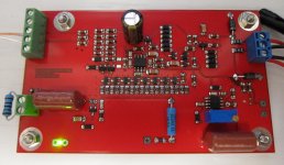
Apologies. I did not intend to offend. You are right that output is essentially single-ended. I'm obviously getting rather frustrated. I will put this down for a day and then take another look at your diagram. I have attached a graphic of the current setup I am using.
Attachments
FWIW with respect to the line input board I am attempting to measure, a diyAudio colleague "astx" measured the board with his Panasonic/Linear VP-7723D spectrum analyser. He said this about his measurements:
"-132dB A weighted referred to 4 Vrms RCA input - my measurement limits"
I make 4Vrms = 14.26 dBu and so I believe he measured -118 dBu A-weighted (20Hz-20kHz). So I have a reasonable degree of confidence that the board itself functions okay (unless of course I have damaged something populating my own two boards!).
The best I am measuring currently is about -105dBu.
FWIW with respect to the line input board I am attempting to measure, a diyAudio colleague "astx" measured the board with his Panasonic/Linear VP-7723D spectrum analyser. He said this about his measurements:
"-132dB A weighted referred to 4 Vrms RCA input - my measurement limits"
I make 4Vrms = 14.26 dBu and so I believe he measured -118 dBu A-weighted (20Hz-20kHz). So I have a reasonable degree of confidence that the board itself functions okay (unless of course I have damaged something populating my own two boards!).
The best I am measuring currently is about -105dBu.
The Panasonic/Levear VP-7723D is not a spectrum analyzer, it is a THD analyzer. It can measure the DUT S/N ratio, however it cannot measure the noise spectral density. I have no idea what those numbers are about, but they are certainly not comparable with what you are trying to measure using the sound card (PSD). It's apple and oranges.
I understand the VP-7723D can short the input to the DUT (via an internal relay) and that this was how the measurement was conducted. No input and surely you have just N.
The VP-7723D presents a wideband measurement and I understand Toni used 20Hz-20kHz and an A-weighting as mentioned above. He expressed his results with respect to 4Vrms and I converted these to dBu. Was my conversion correct?
I understand that for ARTA, albeit I am trying to get a positive confirmation, the upper limit of the graphed range sets the upper limit of the measurement bandwidth. There's a setting for the low pass filter which I had set to 20Hz. When I set the graphed range from 20Hz to 22kHz, the best wideband noise measurement I have achieved is -105dBu.
I've been chatting with Toni about any and all possible differences in his test setup. Clearly he is shorting the input to the DUT within the Levear. As he still has a single-ended cable connected to the input of the DUT (from the Levear) he connects its screen to GND on the DUT via a 10R resistor. However, there's no direct analogy to my test setup as I am shorting the input to the DUT directly at the board and I don't have any input connectors to it. (When this line input board is implemented in the amplifier I would place an RC network from RCA jack cold to chassis as suggested by Bruno in his article.)
The only other difference in the test setup (of course other than the fact he is using the Levear and I am using this pre-amp, an ESI Juli@ sound card and ARTA) appears to be that he also loaded the output of the DUT with a 2k resistor to ground. I have not loaded the DUT with anything other than the pre-amp. I will have a look at this next.
(The reason why I have the pre-amp in the mix is to achieve a lower noise floor for the noise measurement. I recognise I can't do THD+N measurements with it because I don't have the ability to notch out the fundamental after the pre-amp.)
Last edited:
he also loaded the output of the DUT with a 2k resistor to ground. I have not loaded the DUT with anything other than the pre-amp. I will have a look at this next.
Well that was interesting. With a 2k resistor added across the SE output connector pins of the DUT (line input board), my wideband noise measurement fell to -113.6dBu unweighted and -116.3dBu A-weighted. Its current consumption (as measured by my bench PSU) almost halved to 50mA.
Need to think about why this is so...
(FYI the input impedance of the amp I am building is 8k.)
It's now clear that this DUT board needs a minimum load. I tested up to 10k and it was fine, but the output op amps can easily drive 600 Ohm loads so perhaps settling on an "on-board" load of more like 2.2K Ohms makes sense. Conveniently there is provision on the board for doing dropping in the additional resistor to ground required.
Samuel, I know you have tested another implementation of Self's low noise balanced to single-ended line input. I wonder if that implementation needed a minimum load as well.
Regarding measurement setup and the use of the pre-amp (more important to this thread) I found I definitely needed to connect the test lead shield for best results (to DUT signal ground when measuring and to the alligator clips when shorting them to measure the noise floor which was about -128dBu unweighted 20-22k). Connecting the pre-amp board's GND to its chassis was definitely not good in my setup. There may be gains to be had by further optimising the connections to and from the pre-amp, either Bruno's suggestion of RC networks for incoming single-ended cable shields or perhaps the other suggestions made by Waly. I think my use of Neutrik EMC series connectors was about the minimum one would want to use. To be explored. And of course environmental shielding and management makes sense (lights off, mobile phones off, wifi networks off etc). As currently implemented, the measurement noise floor was not a limiting factor in the pre-amp's first piece of work.
Thanks for everyone's help.
Last edited:
Gents, what's the situation with regards to PCBs for this project? I haven't read the whole thread, but is there a group buy or does anyone has boards available?
Jan
Jan
Gents, what's the situation with regards to PCBs for this project? I haven't read the whole thread, but is there a group buy or does anyone has boards available?
Jan
Hello Jan,
Sam Groner and I have struck an agreement. Per that agreement I will soon stock an inventory of PCBs for this project as well as for his (soon to be released) low noise oscillator.
If anyone here is interested please drop me a note to that affect.
Hello Jan,
Sam Groner and I have struck an agreement. Per that agreement I will soon stock an inventory of PCBs for this project as well as for his (soon to be released) low noise oscillator.
If anyone here is interested please drop me a note to that affect.
Hi Carl,
Good initiative! Let me know when they are available,
Jan

Another build
There was some discussion as to whether the performance specified in the Linear Audio article was realistic. I'm curious to know also, so I guess the best way is to build one and see for myself.
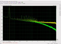
Attached an ARTA measurement of the noise level, the green one was noise measurement of a 1k resistor, the yellow one was for an shorted input. I've yet to find a metal chassis for it so there is some 50Hz pickup (despite I already tried to cover it with a metal lid).
Ignoring the 50Hz hum and it's harmonics, I think the result are pretty close to what's indicated on Fig.14 of the article 🙂
There was some discussion as to whether the performance specified in the Linear Audio article was realistic. I'm curious to know also, so I guess the best way is to build one and see for myself.
Attached an ARTA measurement of the noise level, the green one was noise measurement of a 1k resistor, the yellow one was for an shorted input. I've yet to find a metal chassis for it so there is some 50Hz pickup (despite I already tried to cover it with a metal lid).
Ignoring the 50Hz hum and it's harmonics, I think the result are pretty close to what's indicated on Fig.14 of the article 🙂
Attachments

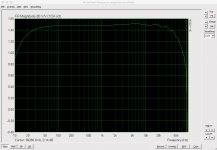
I wanted to check the preamp gain. I purchased some 0.1% tolerance resistors, 200k Ohms and 20 Ohms, and constructed a simple 80db attenuator. My signal generator has a stated amplitude accuracy of +-2% of set value +- 2mV (1kHz sine wave). I calculated that with an input stimulus from the signal generator of 1dBV (3.174Vpp) this should give me an accuracy of +-2.3% or so. I could lower the accuracy range by increasing the level and thereby reducing the impact of the fixed +-2mV but this is good enough for me. Of course my sound card's frequency response is also a variable but likely rounding error for most frequencies (attached).
I took 28 measurement readings in ARTA with stimulus frequencies of 50Hz, 100, 200, 300, 400, 500, 600, 700, 800, 900, 1k, 2k, 3k, 4k, 5k, 6k, 7k, 8k, 9k, 10k, 20k, 30k, 40k, 50k, 60k, 70k, 80k, 90kHz. I set ARTA's spectrum analyser to display dBV/SQRT(HZ) with the FFT settings of Fs=192kHz, FFT=131072, Window=uniform (which gave the narrowest peak).
The lowest result was -84.41dBV @ 8kHz while the highest was -80.76 @ 400Hz. The average was -82.00 dBV.
I conclude from this that the gain of my preamp is closer to 58dB and not 60dB, a voltage ratio of 794 rather than 1,000.
Attachments
Can you repeat that with a 60 Ohm resistor (2*120 par)? = 1nV/rtHz
It irritates me that there is absolutely no 1/f noise visible. The shorted trace
should rise below 500 to 1500 Hz and the 1K trace should rise below
the frequency where it is hit by the "shorted" trace.
These here are 16 BF862 @ 44mA total:
< https://www.flickr.com/photos/137684711@N07/29965414644/in/album-72157662535945536/ >
The shorted trace is 10 dB below 1 nV or +/- 330 pV/rtHz
There is an artificial high pass at 30 Hz.
The 1/f corner is a property of the transistor, there is not much one can do
against it.
regards, Gerhard
I conclude from this that the gain of my preamp is closer to 58dB and not 60dB, a voltage ratio of 794 rather than 1,000.
This preamp is using negative feedback, and the gain is governed by the resistor ratios of R105 and parallel combination of R107-R117.
With 0.1% resistors, if your gain is off by 20%, I would wonder if 2 of your 10R resistors are problematic.
I'll do that in the coming weekend (it's 2:00am in where I live now)Can you repeat that with a 60 Ohm resistor (2*120 par)? = 1nV/rtHz
You'll have to ask Samuel on how he overcomes this, it's beyond my level to answer, but the exceptional 1/f corner frequency of less than 10Hz is highlighted in section 11 of his article.The 1/f corner is a property of the transistor, there is not much one can do against it.
Last edited:
This preamp is using negative feedback, and the gain is governed by the resistor ratios of R105 and parallel combination of R107-R117.
With 0.1% resistors, if your gain is off by 20%, I would wonder if 2 of your 10R resistors are problematic.
I'll take a look!
I have also encountered another oddity while using the preamp as discussed in the split thread "measuring PSRR". I've been using it to try to evaluate the PSRR of a regulator circuit I've been working on and in so doing have also tested the PSRR of an LM317. Where one would expect to see a 20dB per decade reduction in PSRR from about 10kHz onwards, the measurements do not show this. Furthermore, at one stage I coupled the preamp to the output of an amp build I have been working on which had its input shorted with 100R. Curiously, the noise measurement spectrum showed a 20dB / decade rolloff from circa 10kHz onwards whereas when I took exactly the same measurement without the preamp (just using a direct coupling of the amp output to my sound card) there was no such rolloff in noise. (Ignore for the moment the overall bad noise and focus on the relative profiles of the noise spectrum.)
The two completely different situations lead to the same suggestion that if the DUT is loaded somehow it causes a severe discrepancy in the frequency response of the preamp. I'm still trying to figure out why. I don't recall this being the case when the amp was simply dead shorted but I would have to check again to be sure.
Attachments
Last edited:
- Home
- Design & Build
- Equipment & Tools
- Groner's Low noise measurement amp from Linear Audio vol 3 - spare boards?