1K resistor (of good quality, not carbon comp) will provide a nice 4 nV/rt(Hz) reference, upon which "we" can estimate the noise performance of your preamp.
Longer traces is better, as you'll asymptote to a flatter noise density above 1 kHz. I'm unsure whether 44.1/48/88.2/96/192 is the best for your sound card (ADC and implementation sensitive), but I assume you'd want the preamp's noise performance out past 20 kHz. (Although that might be AA filter limited.)
Do not take me as gospel here, but think one of the Blackman is going to be best here.
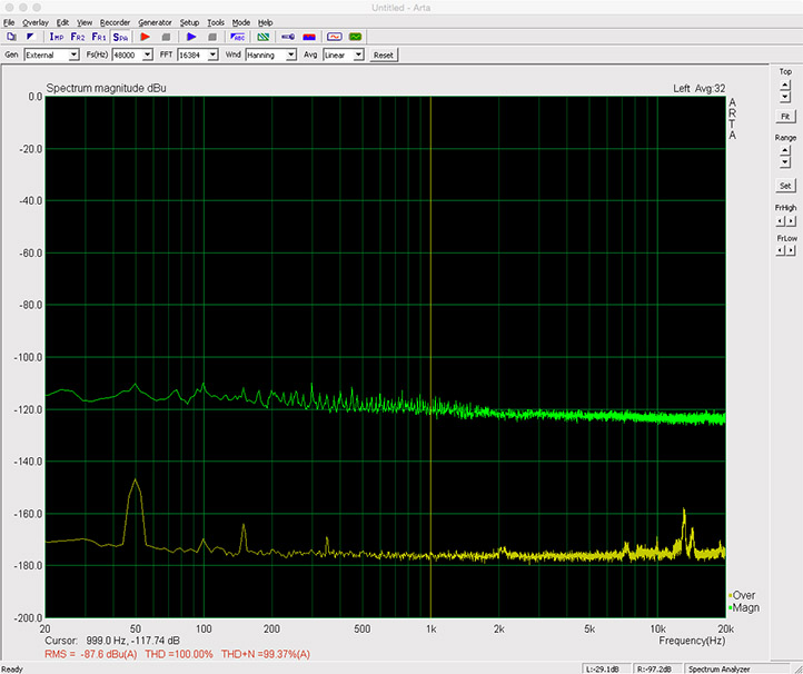
1k resistor (noise floor remeasured as well). FWIW the FFT was very volatile.
Something is not right. Please state how you measured the 1k resistor, 4nV/rtHz should be at -148dB
I presume the yellow trace is the sound card with the input shorted?
Yellow trace is "DUT to pre-amp input cable" alligator clips shorted.
Green is with alligator clips holding 1k resistor. (2% metal film)
Green is with alligator clips holding 1k resistor. (2% metal film)
Yellow trace is "DUT to pre-amp input cable" alligator clips shorted.
Green is with alligator clips holding 1k resistor. (2% metal film)
I don't follow. What is "DUT to pre-amp input cable"? What are the "alligator clips", the sound card input? If so, are you sure the resistor is 1k (appears as 4.7k from the noise measurement).
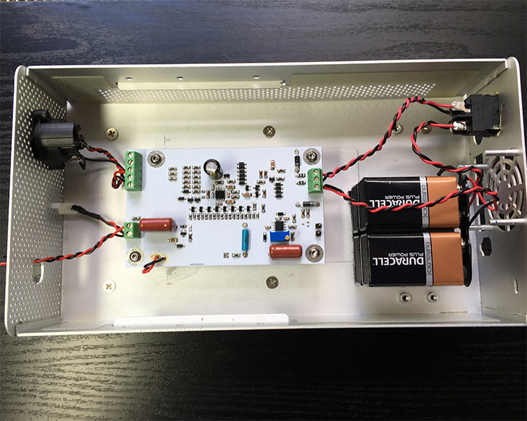
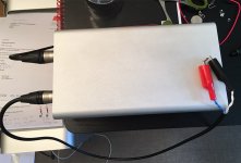
The preamp board and the 9V batteries powering it are now in an enclosure - see previous posts.
This enclosure has two XLR jacks for connection to the outside world. One "output" jack uses a balanced XLR (preamp end) to balanced phono/TRS cable to connect to the Juli@ sound card. The other "input" jack needs to connect to whatever is going to be measured. I have a cable terminated with an XLR connector at the preamp end and clips at the other. (On this cable, the sleeve/shield is only terminated at one end, to the preamp enclosure.)
Resistor measures 1k Ohms.
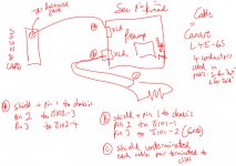
SGK--even a MS Paint version of what you're describing? I'm not putting it together.
Neither do I, and I need to sleep now...
Last edited:
I need to sleep also. In the morning I need to (at least) check my input and jack wiring. If I short connector J101 on the board (within the enclosure) I get the attached. Green = 1k resistor. Yellow = shorted with 1mm copper wire.
The 1k resistor still isn't -148dB. To get circa -148dB I need to lower the preamp gain setting in ARTA by a factor of 10 to 100 (rather than 1000)....
The 1k resistor still isn't -148dB. To get circa -148dB I need to lower the preamp gain setting in ARTA by a factor of 10 to 100 (rather than 1000)....
Attachments
Last edited:
I need to sleep also. In the morning I need to (at least) check my input and jack wiring. If I short connector J101 on the board (within the enclosure) I get the attached. Green = 1k resistor. Yellow = shorted with 1mm copper wire.
The 1k resistor still isn't -148dB. To get circa -148dB I need to lower the preamp gain setting in ARTA by a factor of 10 to 100 (rather than 1000)....
Ummm... You are good, my bad, 1k is -168dB, -148dB is 10k. Be back tomorrow (er, later today)
The noise changes with root resistance.
To increase, or decrease, the noise by a factor of 10 (20dB) one needs to use a resistance factor of 100, i.e. 10r gives -188dBV (0.4nV/rtHz), or 100k gives -148dBV (40nV/rtHz)
I'm not long up and don't have an excuse if that is wrong.
To increase, or decrease, the noise by a factor of 10 (20dB) one needs to use a resistance factor of 100, i.e. 10r gives -188dBV (0.4nV/rtHz), or 100k gives -148dBV (40nV/rtHz)
I'm not long up and don't have an excuse if that is wrong.
Indeed. Looks to me like the pre-amp has about the right level of gain. I see that a 1kR resistor has a noise spectral density of 4.0578nV/rtHz at 25C over 20Hz to 20kHz = -168dB voltage gain. If the pre-amp gain is off, it isn't off by much. I think I can just leave the pre-amp gain setting at a nominal 1000.
What I am not sure about is how ARTA determines the bandwidth etc for its RMS figures (in red). One can set the frequency range for the graph, but it would appear the RMS figure is calculated off a different range or something as it bears no resemblance to the green plot. One can turn the weighting on or off and select from A, B and C weighting. With no weighting it reads -124.1 dBV for the above measurement. There's a box to set the "low cut off" for distortion analysis.
Now to try to figure out whats wrong with my test leads/XLR jack such that it screws up the measurement massively when a resistor is measured at the end of the cable and outside the pre-amp enclosure...
The noise changes with root resistance.
To increase, or decrease, the noise by a factor of 10 (20dB) one needs to use a resistance factor of 100, i.e. 10r gives -188dBV (0.4nV/rtHz), or 100k gives -148dBV (40nV/rtHz)
I'm not long up and don't have an excuse if that is wrong.
Correct.
Now to try to figure out whats wrong with my test leads/XLR jack such that it screws up the measurement massively when a resistor is measured at the end of the cable and outside the pre-amp enclosure...
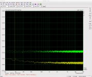
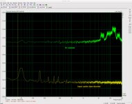
I can't find a problem with the wiring of the input XLR jack or cable. This must be environmental pollution or similar. Pic 1 yellow shows the noise floor when I simply short the (input) XLR jack with 1.5mm copper wire from the exterior of the enclosure. Pretty good. Pic 1 green is when I connect the shielded 'input' cable to the XLR jack and simply connect its clips together at the other end. Some 50Hz contamination of the noise floor but not horrific.
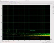
Now pic 2 where the yellow is the same the green in pic 1. Green in pic 2 is what I get when I detach the clips from each other and short them with a 1k resistor, now the resistor is suspended in the clips which in turn are resting on the enclosure (as they were when directly shorted). See 3rd pic. Markedly worse and clearly not good enough to measure the noise of the resistor. I'm rather surprised that it is so bad given the shorted clips suggest the general noise floor is low enough.
What am I missing?
Attachments
I'm not sure you can expect to measure at these levels without proper screening. Capacitive coupling from e.g. fluorescence lamps is significant with a 1k source impedance.
I'm using a panel sheet on my work bench table and an old metal cookie box, both grounded. What's left is mostly magnetic inference which can be reduced by orientation and distance.
Samuel
I'm using a panel sheet on my work bench table and an old metal cookie box, both grounded. What's left is mostly magnetic inference which can be reduced by orientation and distance.
Samuel
Ok so I there's nothing wrong with the pre-amp implementation. It appears we have established that the pre-amp has, at least broadly, the correct gain. It's just if we want to measure really low then we need to take stricter environmental precautions.
So back to post 94... I repeat the image below:
The reason why I selected a scale of dBu is because that is what Self used in his text. He states that he measured his implementation of this circuit at -119.5dBu. I haven't yet figured out how to get a credible single figure measurement, but it would seem to me that I can rely on the scale (knowing that the amp measures a 1K resistor 'well') and that my implementation of this circuit is performing to expectations.
Fair?
Or do I need to be taking even more careful environmental precautions to measure a circuit such as this? I guess I could find another enclosure, sit the DUT inside it and feed power and other cables to it through holes in the enclosure...
The reason why I selected a scale of dBu is because that is what Self used in his text. He states that he measured his implementation of this circuit at -119.5 dBu.
I'm not sure if you're considering the difference between a wideband noise measurement (e.g. 22 Hz to 22 kHz) and a noise spectral density measurement. You need to relate one to the other by means of the measurement bandwidth.
The -119.5 dBu quoted by Self is a wideband noise measurement, presumably in a 22 Hz to 22 kHz bandwidth. This is 820.5 nV or -121.7 dBV. To get a noise spectral density, you divide by the square root of the measurement bandwidth (21.978 kHz). This gives 5.535 nV/rtHz, -162.9 dBu/rtHz or -165.1 dBV/rtHz. These are the figures you should read in ARTA in spectral density mode (again: spectral magnitude is useless for noise measurements).
Note that this assumes pure white noise. As 1/f content etc. is usually modest, this should hold well.
Also the figure quoted by Self might be referred to the input, so you need to consider the gain of the DUT (multiply the 1000x scaling for ARTA with the gain of the DUT).
I don't know ARTA so I'm no help with getting wideband results.
Samuel
I'm probably not considering enough things!
So I need to look in spectral density mode and ignore dBu scaling? I only switched to this at Waly's request to reexamine the 1k resistor. All I have been doing is eyeballing the FFT in ARTA with scaling set to dBu (because Self reported results in dBu) looking across the spectrum from 20Kz to 20kHz (if the difference between this range and 22-22k is significant I can amend the defaults in ARTA but I presumed it wasn't) and seeing that it is "in the zone".
I was hoping the RMS number would be an average of sorts across the measurement bandwidth and comparable to the single measurement provided by Self, but it seems way off the mark. The ARTA user manual can be found here with the spectrum analyser section beginning on pg 22 and RMS level covered on pg 36. I'm afraid to say that at this point the content goes completely over my head. It doesn't seem to work when the input signal isn't way above the noise floor.
(again: spectral magnitude is useless for noise measurements)
So I need to look in spectral density mode and ignore dBu scaling? I only switched to this at Waly's request to reexamine the 1k resistor. All I have been doing is eyeballing the FFT in ARTA with scaling set to dBu (because Self reported results in dBu) looking across the spectrum from 20Kz to 20kHz (if the difference between this range and 22-22k is significant I can amend the defaults in ARTA but I presumed it wasn't) and seeing that it is "in the zone".
I was hoping the RMS number would be an average of sorts across the measurement bandwidth and comparable to the single measurement provided by Self, but it seems way off the mark. The ARTA user manual can be found here with the spectrum analyser section beginning on pg 22 and RMS level covered on pg 36. I'm afraid to say that at this point the content goes completely over my head. It doesn't seem to work when the input signal isn't way above the noise floor.
I'm probably not considering enough things!
So I need to look in spectral density mode and ignore dBu scaling? I only switched to this at Waly's request to reexamine the 1k resistor. All I have been doing is eyeballing the FFT in ARTA with scaling set to dBu (because Self reported results in dBu) looking across the spectrum from 20Kz to 20kHz (if the difference between this range and 22-22k is significant I can amend the defaults in ARTA but I presumed it wasn't) and seeing that it is "in the zone".
I was hoping the RMS number would be an average of sorts across the measurement bandwidth and comparable to the single measurement provided by Self, but it seems way off the mark. The ARTA user manual can be found here with the spectrum analyser section beginning on pg 22 and RMS level covered on pg 36. I'm afraid to say that at this point the content goes completely over my head. It doesn't seem to work when the input signal isn't way above the noise floor.
SGK, IMO you are trying to digest more than your stomach can handle. You would need to sit back, then begin reading the ARTA manual and try to understand the features of ARTA and the background of noise and noise measurement.
At this point, IMO your preamp seems to work fine, although you got about 20-30% worse noise performance compared to Mr. Groner's Linear Audio paper (0.45nV/rtHz vs. 0.35nV/rtHz @ 10kHz and 1nV/rtHz vs. 0.7nV/rtHz @ 20Hz).
The artifacts you got when measuring the 1k resistor are likely due to a TV or computer monitor, some of these are radiating at ~16kHz and the cable is picking up the junk. To further advance, you need to re-thing the grounding and shielding of your setup; that's not easy, in particular when you also have to deal with balanced to single ended conversion. I'm sorry I'm unable to help you further, other than reminding you that the best approach is to divide the issue in small chunks that are easy manageable. Grounding is one of those, shielding is another and of course some sort of crash course in noise and noise measurement would help.
- Home
- Design & Build
- Equipment & Tools
- Groner's Low noise measurement amp from Linear Audio vol 3 - spare boards?