I'll take a look!
I checked all the resistors and they seem ok. R105 measures exactly 1k and measuring across R117 reads 1.0R. Of course I'm not sure just how accurate my DMM is at measuring 1R. (The only one that would appear off by a meaningful amount is R215 which I have now replaced.)
Samuel comments in his article that the gain was consistently less than 60dB. Perhaps he can comment as to just how much lower he experienced.
Have you checked gain in your build?
Last edited:
Have you considered the 3dB loss into a 50 Ohm load?
The feedback divider is absolutely ok.
The only thing I could imagine is that the current source
is too soft, resulting in less than optimum loop gain.
Too late to analyze that now. bed time.
@cwtim01:
In the plot, I see a 1/f corner of 100 Hz, not 10 Hz,
even though the text says differently.
Even that seems low for this transistor. It might well
be that the 1/f frequency is higher and is only masked
by a wideband noise source, maybe missing OL gain.
(as far as contributed by the FETs)
That would really be good news since one could improve
the noise in the flat region.
Have a good night, Gerhard
Last edited:
I wanted to check the preamp gain. I purchased some 0.1% tolerance resistors, 200k Ohms and 20 Ohms, and constructed a simple 80db attenuator.
Getting 80 dB of accurate attenuation is not really that easy. The 20 Ohm resistor may not be really flat with frequency, nor the 200K. its usually better to do it in stages and keep the impedances as low as possible. Stray capacitance can throw you off if one leg is 200K.
I built a similar attenuator from a 50 Ohm balanced source to a short length of wire to get it really stable and predictable. It works and was completely insensitive to load. 2 25 Ohm resistors and about 1/2" of 20 AWG wire. You really need a milliOhmeter to get it close and then test it.
This is also useful for testing noise floor since the wire's noise is way below any amplifier and you can add a signal to verify gain etc. Then just increase the resistance across the input until the noise rises 3 dB. It helps to have a low resistance decade resistor.
For a 600 Ohm source you could use a 600 Ohm series resistor and a .12 Ohm resistor in parallel. make sure the connections are across the .12 Ohm resistor. The wire will add significantly to the resistance. This combination should give -80 dB from the open circuit voltage of a 600 Ohm source.
Another thought- measure the effective input impedance of the amp. The easy way is to connect a series resistor of approx the input Z and measure the output voltage. You should get a 6 dB loss compared to a short when the resistance matches the input impedance.
You will also get a good idea of the input C.
I use the ESI Juli for a lot of measurements and its response and distortion is low enough for most things. The opamps really can't be swapped because of the odd footprint. The PCB's are also quite fragile.
You will also get a good idea of the input C.
I use the ESI Juli for a lot of measurements and its response and distortion is low enough for most things. The opamps really can't be swapped because of the odd footprint. The PCB's are also quite fragile.
gerhard, 1audio - thanks for all the help but, please, more slowly as I am on a steep learning curve here. I'm a relative newbie to this.
I have not considered any loss into a 50 Ohm load. 😕
I understood the target input impedance of the preamp ("LNA") to be >100k Ohms. Here Waly asked that I measure the open input noise of the LNA to provide an estimate of input impedance. When I made the measurement then I got a LF noise level of circa -160 dBV. I just redid this test and got similar results. He suggested that a LF noise level of -160dBV (10nV/rtHz) meant an input impedance closer to 6500R i.e. way off. (I calculated closer to 6k but whatever.) [Note we see that roll-off again.] 1audio, I'm afraid I don't think I follow your suggested test of input impedance.
Elsewhere Gerhard rightly suggests using the ESI Juli@ XTe sound card as a stimulus rather than my Rigol DG1022. I will look at that once I have my head around the other issues discussed here.
Attachments
Last edited:
I have not considered any loss into a 50 Ohm load. 😕
The output of the amplifier has a 51 Ohm resistor. If you connect
a 50 Ohm scope for example, you will see only half the voltage
on the scope since the other half is across the 51R.
That's -6 dB.
The advantage is that you have a properly terminated coax cable
and the op amp does not see directly the capacitance of the cable,
which can be large. Op amps do not like capacitive load.
I think that was not me with the stimulus proposal?
Good point, though it would have to be a fair bit. A little sim with an estimated parasitic 3 pF in parallel to both 200k and 20R (-80.46 dB nom) shows a bit of a bump in the ultrasonic region, but it takes up to 40 kHz for +0.1 dB. At the end of the day, we're still not anywhere near 1 or even 10 Megohms here.Getting 80 dB of accurate attenuation is not really that easy. The 20 Ohm resistor may not be really flat with frequency, nor the 200K. its usually better to do it in stages and keep the impedances as low as possible. Stray capacitance can throw you off if one leg is 200K.
Going to 2 stages of 20k/200R each (-80.7 dB nom) pushes that point to >280 kHz if need be.
None of this explains an HF dip.
Probably yours truly over here.I think that was not me with the stimulus proposal?
http://www.diyaudio.com/forums/soli...gain-balanced-input-stage-19.html#post4889997
Probably yours truly over here.
http://www.diyaudio.com/forums/soli...gain-balanced-input-stage-19.html#post4889997
Doof. My apologies to you both!
The output of the amplifier has a 51 Ohm resistor. If you connect
a 50 Ohm scope for example, you will see only half the voltage
on the scope since the other half is across the 51R.
That's -6 dB.
Yes, sorry what I meant is doesn't the input impedance of the sound card determine how much is dropped over the 51R at the output of the preamp? I'm not following why the drop would be anything close to 50%.
None of this explains an HF dip.
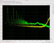
BTW I don't think it is a "dip" but rather a 20dB per decade decline in response somewhere coupling with a bump in the sound card noise. Shorted sound card pic attached.
Attachments
Yes, sorry what I meant is doesn't the input impedance of the sound card determine how much is dropped over the 51R at the output of the preamp? I'm not following why the drop would be anything close to 50%.
Does it make a change if you connect the other channel of the sound card also?
assuming it's stereo. Or another known resistor?
@cwtim01:
In the plot, I see a 1/f corner of 100 Hz, not 10 Hz,
even though the text says differently.
Even that seems low for this transistor.

What I said myself in this thread and elsewhere... 10Hz corner frequency is out of this world.
Hmm. I might just have found a possible source of the roll-off - although I don't understand it (nothing new there).
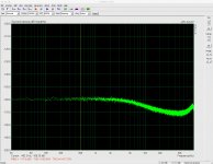
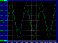
I coupled the preamp to the output of the amp build sitting on my desk. The first pic is how I had coupled it before. I am using balanced TRS connections on my Juli@. At the preamp output I have an XLR with pin 2 wired to preamp J102 3 and pin 3 wired to preamp J102 4. Pin 1 is wired to preamp enclosure. (Yes, I realise the preamp is single-ended and I could redo my cabling and reverse the board on the Juli@ to single-ended RCA output connectors.) Yellow trace is without the preamp. The green trace is with the preamp. (To get the two traces to generally line up in the second pic (see below) I had to change the gain in ARTA from a nominal 1000 to my calculated 794.
The preamp is powered by a bank of 9V batteries for nominal +- 18V. There is no connection from preamp circuit board ground to the preamp enclosure.
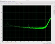
For the second pic I connected the preamp enclosure to the amp (DUT) chassis in turn connected to safety earth i.e. I grounded the preamp chassis. No more rolloff in the noise profile.
When I was doing the regulator tests, I placed the regulator DUT, the rail driver, the load and the preamp (within its enclosure) all within a further enclosure. The rail driver was powered by my bench PSU. The output of the reg DUT was connected to the preamp input via coax. I had not connected either of the two enclosures to earth.
PS: yes, the amp output has a lot of noise but that's largely just due to way it is heaped together on my desk at the moment!
I coupled the preamp to the output of the amp build sitting on my desk. The first pic is how I had coupled it before. I am using balanced TRS connections on my Juli@. At the preamp output I have an XLR with pin 2 wired to preamp J102 3 and pin 3 wired to preamp J102 4. Pin 1 is wired to preamp enclosure. (Yes, I realise the preamp is single-ended and I could redo my cabling and reverse the board on the Juli@ to single-ended RCA output connectors.) Yellow trace is without the preamp. The green trace is with the preamp. (To get the two traces to generally line up in the second pic (see below) I had to change the gain in ARTA from a nominal 1000 to my calculated 794.
The preamp is powered by a bank of 9V batteries for nominal +- 18V. There is no connection from preamp circuit board ground to the preamp enclosure.
For the second pic I connected the preamp enclosure to the amp (DUT) chassis in turn connected to safety earth i.e. I grounded the preamp chassis. No more rolloff in the noise profile.
When I was doing the regulator tests, I placed the regulator DUT, the rail driver, the load and the preamp (within its enclosure) all within a further enclosure. The rail driver was powered by my bench PSU. The output of the reg DUT was connected to the preamp input via coax. I had not connected either of the two enclosures to earth.
PS: yes, the amp output has a lot of noise but that's largely just due to way it is heaped together on my desk at the moment!
Attachments
Last edited:
Have you checked gain in your build?
I used a simpler method to check the gain, a voltage divider formed by a 8R2 and 5K6 resistor (just because they lie around my bench, and 1:684 attenuation ratio after measurement of the resistors by a 4-wire DMM).
Then I feed a 684mV input into the divider, send the attenuated 1mV signal into the LNA, and measure the input/output with a scope -> and I get 1V at the LNA output. So I suppose my gain is around 1000. I tried that at numerous frequencies from 100Hz to 20kHz and gain is around the same.
Attachments
That is completely undefined. At least the thermal noise of the 200Meg input
resistor as far as it is not shunted by stray & transistor capacitance.
Since the input needs only voltage and nearly no current, it will pick up
every stray field that comes close. First class shielding is required.
I see for example a lot of noise from the LED ring light of the stereo microscope.
The LEDs are pulsed for intensity control.
Last edited:
Probably yours truly over here.
http://www.diyaudio.com/forums/soli...gain-balanced-input-stage-19.html#post4889997
It would appear that for me to reliably use the sound card as the stimulus I would need to purchase a very good quality voltmeter/DMM in order to calibrate the output volume. I don't think I can rely on my free UNI-T UT120A. (Recommendations on quality DMMs that don't cost the earth appreciated.)
I just ordered a Brymen BM869 after reading the glowing review on EEVblog. 500,000 counts (!), 0.02% accuracy, built like a brick dunny. I bought it from the TME website in Poland, paid GBP 167 plus shipping. Expected delivery on Tuesday.
http://www.brymen.com/product-html/cata860/BM860_Catalog.pdf
BM869S BRYMEN - Digital multimeter | TME - Electronic components
http://www.brymen.com/product-html/cata860/BM860_Catalog.pdf
BM869S BRYMEN - Digital multimeter | TME - Electronic components
- Home
- Design & Build
- Equipment & Tools
- Groner's Low noise measurement amp from Linear Audio vol 3 - spare boards?