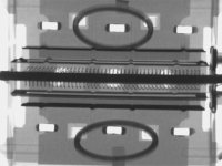
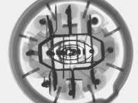
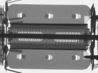
Side view, through the "alignment holes" and beam formers.
The rectangular punched holes seem to be what holds the
plate halves together, and the entire wing some sort of sink.
You may notice the wing intrudes inside, almost up to the
very window of the beam former. This is clearer in another
shot.
The rectangular punched holes seem to be what holds the
plate halves together, and the entire wing some sort of sink.
You may notice the wing intrudes inside, almost up to the
very window of the beam former. This is clearer in another
shot.
Attachments

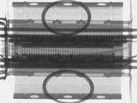
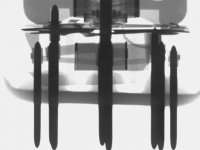
Interesting... I just now notice three rectangular windows
in each beam former. Hold this thing to a light, yep! I can
see right through the other side (no xray needed)...
I still don't know with any certainty what purpose they serve?
And what about that inner ridge down the middle each plate?
Is that one of them mysterious Barkhousen thingamabobbers
I've occasionally heard whispered of in dark corners?
kenpeter said:Interesting... I just now notice three rectangular windows
in each beam former. Hold this thing to a light, yep! I can
see right through the other side (no xray needed)...
I still don't know with any certainty what purpose they serve?
Thanks for the fantastic photos. They're extremely educational. I had been wondering just today about beam power tubes, and why I can see the grids even though I know the beam formers ought to be in the way. I suspected there was some kind of window cut into the beam formers - I hadn't realized the holes were so large, though.
Here's a "pic" (scanner) of a 21JV6,21HB5,17KV6.... plate. The dual internal Barkhausen fins are very obvious on these. Some tubes have small ones as vertical inward wrinkles in the plate sheet metal near the plate supports. Others have spot welded on Bark. fins.
Attachments
A very odd tube plate design is the 6BK5. It's got a trap door in the side of the plate. Apparently it gets bent closed after grid alignment. I don't have a dead one to photo unfortunately.
I haven't figured out how the other tubes with no obvious visual inspection ports were aligned. But maybe they just used a capacitance meter between g1 and g2 and adjusted for a maximum.
Don
I haven't figured out how the other tubes with no obvious visual inspection ports were aligned. But maybe they just used a capacitance meter between g1 and g2 and adjusted for a maximum.
Don
"But maybe they just used a capacitance meter between g1 and g2 and adjusted for a maximum."
I just tried measuring the capacitance while moving the grids around and I don't see much variation. So looks like this technique is out.
Looking at a few non visual-ported horiz. outp. tubes, I notice that they have small metal tabs spot welded to the g1 and g2 grid ends which crimp around the mica plates (at one end only). They must have aligned the grids to the mica before the plate structure was added via the other end. Would be my guess now.
Don
I've been asked to work Saturday, which is usally pretty lax.
So I'll probably bring along more samples to screw with...
I want to compare some pentodes. Identical I think, except
that one type has a sharp cutoff, and the other a remote...
I forget the numbers... If I can't find them, I'll bring a 6BQ5
or whatever jumps out the box at me.
So I'll probably bring along more samples to screw with...
I want to compare some pentodes. Identical I think, except
that one type has a sharp cutoff, and the other a remote...
I forget the numbers... If I can't find them, I'll bring a 6BQ5
or whatever jumps out the box at me.
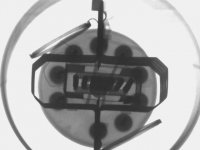
So.. are pentode screens aligned with the control grid, same as beam power tubes?
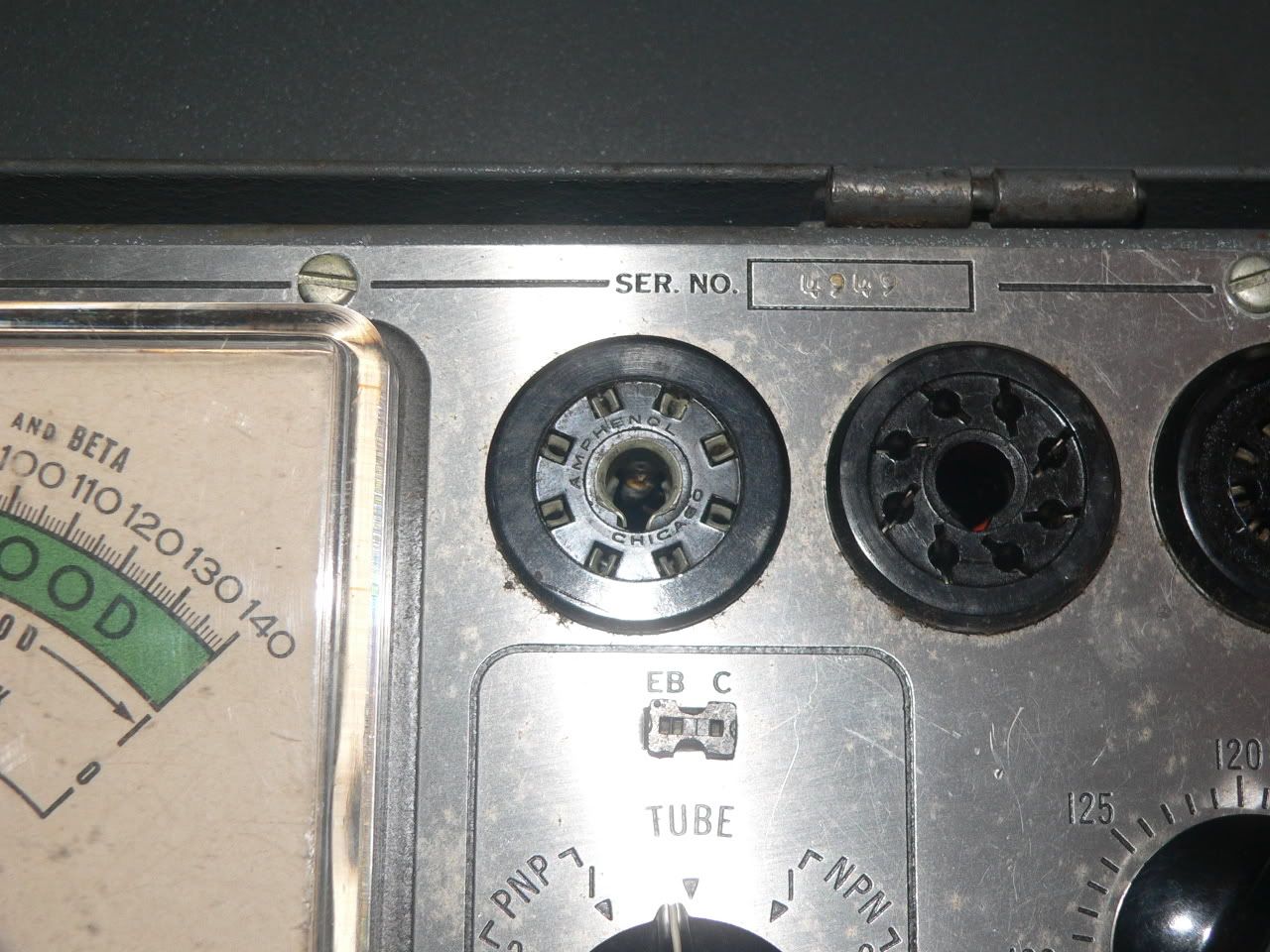
I'm guessing it's an octal based tube. Are those the eight pins I see in the photo? EL34?
I'm guessing it's an octal based tube. Are those the eight pins I see in the photo? EL34?
Nope, not EL34... Maybe not even Octal.
6BQ5 type is still on the list for later.
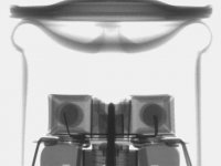
Here they do seem to have aligned G1 with G2, but not G3...
Then again, its kind of odd to find a Pentode with alignment
peepholes. Whatever reason, This one definitely has em...
6BQ5 type is still on the list for later.
Here they do seem to have aligned G1 with G2, but not G3...
Then again, its kind of odd to find a Pentode with alignment
peepholes. Whatever reason, This one definitely has em...
Attachments
The plates look like my 6p3s-e (or Sovtek 5881, or whatever you want to call it). But mine is a beam tube, not a pentode. Weird.

- Status
- Not open for further replies.
- Home
- Amplifiers
- Tubes / Valves
- Grid - Screen Alignment (X-Rays)