Vout now reads 4.936.
I will mess with R1 and see where/if there is a temperature null.
- keantoken
I will mess with R1 and see where/if there is a temperature null.
- keantoken
Yes someone needs to build yours. So some comparisons in the real world can be made.
I did build the beta enhanced version. I started with the high gain KSA/C's , ran into stability issues, used lower gain MJE340/350 devices ... everything was fine. So I did not "diverge" out of malice , but out of necessity. Technically , the 100+ db of loop gain is too much for a balanced VAS . The ampslab BI240 used the MJE's with their inferior beta with good reason. I did not have MPSA/C devices to play with, but I assume they would perform similarly. Beta enhancement works very well on a fixed current source VAS , my 2 blameless clones (AX ,BX) , work flawlessly.
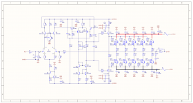
The current mirror active load for the input differential is a cheaper , more stable way to increase the loop gain of the amplifier. I like the idea of "back to back" "blameless" 's. I did not abandon the input cascode/FET version.. (below) all I did was trade the beta enhancements for a simple input stage CM. The near PPM THD (.0005%)and extreme linearity is evident up to 100Khz !!! 🙂
If you build yours , use the mje's or the lowest gain group fairchild you can find.
BTW , I have sprint "aced" ... can do a board an hour now , bom and all ! 😎
If you want, keen .. I will port your beta enhanced variant (CX1.4 ???) Try all 3 !!
OS
Attachments
Last edited:
I recognize there was no malice, simply a difference of paths, which is too often seen as such.
If you can test out the reverse enhancement for merit, I would be in debt (I suspect oscillation will be less dangerous for this version with the natural limit of the reverse buffer, and it would be nice to see how it all plays out). There are zillions of things one can try to fix stability issues, so I suppose I wouldn't be satisfied unless I had a prototype for myself to frankenstein with.
I've increased R1 to 5k, and the circuit already appears more stable, staying close to 4.356V. I will blow it with a fan and see what happens. If Vout decreases, I will know to decrease R1.
- keantoken
Interestingly enough, Vout increased when cooled, which means my 2SC945P must have fairly high beta.
I will have to switch in a new trimmer.
- keantoken
I will have to switch in a new trimmer.
- keantoken
Amazing, my 2SC945 model is PERFECT. Tempco and Hfe are incredibly accurate to the datasheet. Interesting then that I'm still getting an uncompensated tempco at 10k for R1.
- keantoken
- keantoken
Kean if drift is contained enough not to cause problems is no big issue. Noise and phase stability must be primarily good enough.
It looks like with this design we'll be seeing 1-2V drift at max output worst-case, and <1V drift under normal circumstances. Interestingly enough, this figure didn't change much while messing with R1. This is good enough for me, though it would be nice to perfect the design. I want to try using 2SC3503's, and see what changes. I think the next thing I will try is a MOSFET for the CCS, and see if this decreases LF noise.
Noise is below 10uV above 100Hz, and using a 20-turn trimmer for R1 seems to have increased LF noise again. I will replace it with a resistor.
- keantoken
Noise is below 10uV above 100Hz, and using a 20-turn trimmer for R1 seems to have increased LF noise again. I will replace it with a resistor.
- keantoken
could there issues with a very fast and a slightly "nervous" curcuit ?
some seem to prefer a relatively slow curcuit
I suppose a regulation is kind of like a constant on and off "switching"
and that the "switching" introduce something into the following curcuit
some seem to prefer a relatively slow curcuit
I suppose a regulation is kind of like a constant on and off "switching"
and that the "switching" introduce something into the following curcuit
It looks like with this design we'll be seeing 1-2V drift at max output worst-case, and <1V drift under normal circumstances. Interestingly enough, this figure didn't change much while messing with R1. This is good enough for me, though it would be nice to perfect the design. I want to try using 2SC3503's, and see what changes. I think the next thing I will try is a MOSFET for the CCS, and see if this decreases LF noise.
Noise is below 10uV above 100Hz, and using a 20-turn trimmer for R1 seems to have increased LF noise again. I will replace it with a resistor.
- keantoken
It seems as through you are designing a regulator for the medical field or NASA. 😀
Consider , will the typical DIY'er want to adjust 2 trimmers to stabilize his front end rails ? If I put them on the main power board , they(the regulators) should be ready to go "out of the box". I am not saying downgrade to a simple (zener)shunt or cap multiplier .... but something that will stabilize quickly and be VERY reliable. The voltage board deserves the best , I agree... but sometimes it all comes down to a compromise between simplicity , reliability , and time/$$. I measured my actual voltage board and it draws 25mA MAX per rail while I shake the house at 200W... a small load indeed.
Perhaps Salas has a proven simple design that would fit this criteria.
Another idea is to have the regulator as a totally separate board while making the power (OPS) board with the 2 sets of fastons (Vcc1/2 - Vee1/2).It really is a "trainwreck" to have unrectified 120vAC fed directly into your main amp layout.. 😱😱
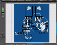
I envision an 8/ TO-247/TO-3P board like this ...
An externally hosted image should be here but it was not working when we last tested it.
with 2- 4700/10k main caps for the OP's and local decoupling for the outputs and voltage board. The voltage board will be at a 90 degree angle with the components facing the user instead of integrated like in the photo above.
A layout like this along with split ground returns is already light years ahead of the goldmund and in the real world leaves you with just transistor noise. If , for some reason, the regulator turns out to be substandard or unstable , one could just redesign/replace. Better than fouling up the whole project.
A good analogy would be a modular gamers PC versus a DELL P.O.S. ... no comparison + you can always upgrade/refit at will.
OS
That is similar to my 200 watt bjt layout. My idea for the aussieamp thin board with the right angle Voltage board will fit 3" or 5" (75/125mm) heatsinks and only extend 3" (75mm) from the heatsink face. (like the last picture/ aussieamp .) REAL small footprint. 🙂This is in the direction of using a VERTICAL mounted input/VAS board and the Front End power would come in from the left.
Comments so I will not get to far into this.
Thanks
Just a single 10" X 3" (250 X 75mm) so the "toner transfer people" can print it out.
OS
Last edited:
could there issues with a very fast and a slightly "nervous" curcuit ?
some seem to prefer a relatively slow curcuit
I suppose a regulation is kind of like a constant on and off "switching"
and that the "switching" introduce something into the following curcuit
Linear regulators only switch literally unless they're oscillating or you do weird things with them. If you see the regulating action as a sort of switching, then you would also have to say the same of NFB amplifiers - the basic idea for both is the same.
As for preferring slower circuits, I wonder if this doesn't have to do with speaker choice. The statement that using zobel is audible would seem to indicate that the speaker interacts with HF damping factor. With a zobel, the speaker effectively "sees" a slower amp. Slower amps tend to have more parasitic output inductance (a natural consequence of BW limiting and stability compensation).
I don't intend to produce a nervous circuit; I want to produce a careful but effective circuit which does not overshoot and is okay with a variety of loads. So far I seem to have succeeded. I have had no problems with stability since adding the output capacitor - currently a 160V 3.3uF lytic. Furthermore, the simulator indicates a benign, natural output inductance characteristic as opposed to super-regulators which achieve high speed at the sacrifice of a 12db/octave rise in output impedance (as opposed to the normal 6db/octave inductor), which causes oscillation into capacitors without enough ESR to limit Q.
Given it's chance, I think this can be a very reliable regulator. It needs one adjustment to set proper output voltage in either case of Jfet or BJT.
I must sleep now,
- keantoken
Last edited:
Actually it wasn't a 12db/octave impedance rise, but the output phase moving above 90degrees that causes oscillation in my experience. IE, anything at or above 6db/octave will have a HF phase larger than 90 degrees (because of parasitic phase anomalies) and you will need resistive bypass.
- keantoken
- keantoken
Last edited:
So there will be boards for:
1. Front end, Input with FET or bipolar and VAS Mosfet or bipolar
2. Back end, either FET or BiPolar, with emitter resistors or not, 3, 4, or more pair
3. Great Front power supply or what ever
4. Standard Backend supply or enhanced
5. Protection or none needed
6. Total IR remote control with lots of LED's and shock absorbers...just kidding
Focus Focus FOCUS
Over the last 2 days I have read the previous ....Ahemmm... therad and arrived to this. 🙄 please do not forget to add the wonderful effects of a front pannel red-blue 'wig-wag' LED setup. 😛
Oh and did I mention I need a really cool looking chrome grill??😀
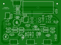
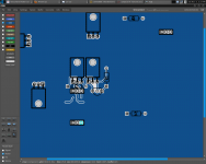
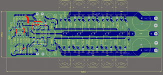
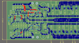
hi guys, i had some free time last weekend and thought of trying to do the layout. this is far from fnished, i just did a quick layout. i'll definitely build this amp.
edit:
the GND is left unconnected. i'm planning to use the top layer (red) as ground plane.
edit:
the GND is left unconnected. i'm planning to use the top layer (red) as ground plane.
Attachments
Last edited:
It looks like your speaker output is on the opposite side to your feedback takeoff. I recommend you move the speaker output to the right of R25. I would put C6 closer to R18 (C3 should be moved in it's place), and C8 should be to the left of R20, R17 and R14. The upper rail power power inputs don't need to be close to R24/26 as C11/12/13/14 already filter the drivers. I would put them closer to R5 and R7.
I would separate the ground planes for signal ground and decoupling, and then join them at speaker return. If the speaker output is taken to the right of R25, and speaker return from the same place, signal ground plane doesn't have to cross through the dangerous power FET area.
You should also be aware that the stability compensation was determined in simulation and may not be optimal. If it oscillates, increase C9.
I will simulate with parasitics inductors and see which parts of layout are more important.
- keantoken
- Home
- Amplifiers
- Solid State
- Goldmund Mods, Improvements, Stability