Easy peasy with a HP7475 plotter, just requires etching one side first and drilling 2 marker holes. (limited to 8" x 12" boards though)
DIY boards are so amateur !
TO-3 boxes even under the HP? I wanna dive in that storage room.
I'm a hopeless wholesale hamster.
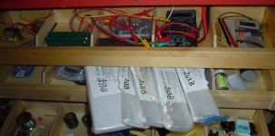
To solve the storage problem i've built closets with Ikea pull-out drawers, 20-section each, 30" wide, 20 drawers in each closet.
Helps a little, i tend to buy chassis and front panels by the dozen for future projects too, transformers, or big rubber amp feet from Apex by the hundred.
(oh my god, i'm an amp Sheik)
YouTube - The Clash - Rock The Casbah
Attachments
We must see a full project of yours someday Jacco. With unobtanium parts everything of course.🙂
Link to Clash won't work BTW. Was in their last gig in 1985 though.
Link to Clash won't work BTW. Was in their last gig in 1985 though.
You think ?
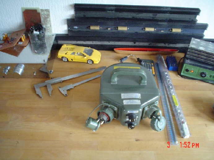
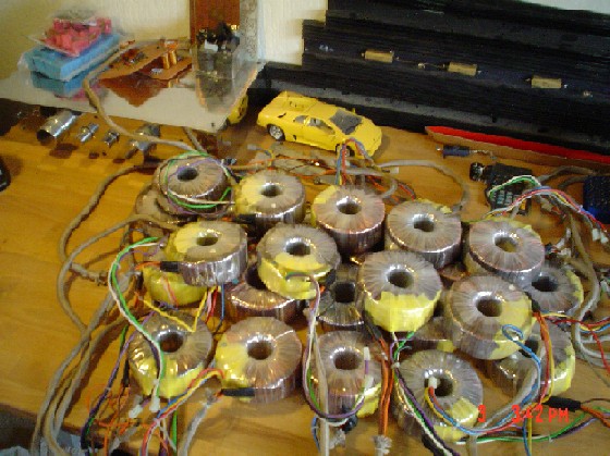
Example of the stuff i built +20 years ago, welded chassis frame, polished and chromed machined 6mm panels, hand engraved, one-off machined and chromed hollow bronze knobs, all DIY moi.
(hand matched MAT02, 0.1% L+R selected RIAA polystyrene, hand made pcb dampers, ear-selected silver plated ptfe hookup wire)
=>http://www.diyaudio.com/forums/atta...87426-pass-monster-separation-1600va.big4.jpg
=>http://www.diyaudio.com/forums/atta...099489659-pass-monster-24-x-300va-toroids.jpg
(the left upper corner part)
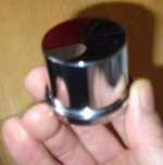
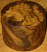
Ah, you like Bling Bling ?
Here's a spare knob, 60mm diameter, polishing chrome drives a person bonkers.
(see why i enjoy your vet guy so much ?)
Others may fancy a CTC BT original knob model more.
Problem for the DIY majority is lack of resources.
Try tell the Mimesucks bunch that their clone will come close only if they use original and closely matched devices only, or $10 each 0R1's.
Which requires a large number of same batch series devices in both cases.
Single individual at this club who does is a nut who clones a €20k amp he already has.
Attachments

The circuit shown in post 644 won't work very well. There is not a stable reference voltage or current anywhere in the circuit.
I think you have misunderstood the operation of the shunt regulator.
R4 in conjunction with Vbe sets the Series CCS current.
J1 in conjunction with 500Vr trim sets the Shunt CCS current.
R4 in conjunction with Vbe sets the Series CCS current.
J1 in conjunction with 500Vr trim sets the Shunt CCS current.
Anderw T,
Yes, but in my view this current reference is not constant from part to part or over temperature changes. In addition, Vbe also is not constant. At best, a very poor regulator; very sensitive to component tolerances and temperature.
Rick
Yes, but in my view this current reference is not constant from part to part or over temperature changes. In addition, Vbe also is not constant. At best, a very poor regulator; very sensitive to component tolerances and temperature.
Rick
Anderw T,
Yes, but in my view this current reference is not constant from part to part or over temperature changes. In addition, Vbe also is not constant. At best, a very poor regulator; very sensitive to component tolerances and temperature.
Rick
Darn EE's - go'n and putt'n all that engerrrrnearing stuff!!😀😀😀
Sawrey, I was waiting for something from you. Salas will have to speak about the stability of the Jfet reference, I was skeptical myself but Salas does this all the time, and the Jfet has a constant .68V drop. Datasheets don't say anything about temperature.
Nico, with a CCS of 100mA feeding the shunt, 70V into 500 ohms draws 140mA - you are turning the shunt regulator off. 70V into 1kohms draws 70mA, which will keep roughly 30mA through the shunt, and this will perform worse than with 60mA through the shunt as it will be used in the circuit with ~40mA load. Test at 100mA CCS with 40mA load and we can compare our results.
May I suggest that if you can't find fault with my simulations and still get worse results, post your simulation schematic so that we can find out what you did different. If you used the 6.8R value for the CCS, that is just a guess it may take some testing to get closer to a 100mA CCS.
Alright, for a ground plane, we need to visualize the loops of current. Let's start at the more dangerous, high frequencies through decoupling, VAS, LTP, Cdom, decoupling, etc at frequencies important for stability. A ground plane parallel to these loops will decrease trace inductance by shorting the trace's self-inductance, but will increase parasitic capacitances. Thus we should also identify positive-feedback miller loops.
- keantoken
The regulator will need adjustment when first powered up. My simulator reads 400mV/C Vout tempco for one model (J2SK170) and 20mV/C tempco (LSK170B) for the other.
- keantoken
- keantoken
Last edited:
Hey, what if we make the top layer the ground plane. Then we can fasten the TO126 devices to the copper plane and use the board as a heatsink.
- keantoken
- keantoken
The regulator will need adjustment when first powered up. My simulator reads 400mV/C Vout tempco for one model (J2SK170) and 20mV/C tempco (LSK170B) for the other.
- keantoken
Zero tempco will be at Vgs=Vp-0.63 as per Erno Borberly. Thus higher Vp Jfets will tend to have this point at Id less than lower Vp ones as derived from their gm curves. Jung asks for proper CCS function a Jfet to have Vds at least 2 times Vp. Since a K170GR will have -0.5Vp, Vbe it nests in is over two times that. Criterion's met. You can lift the Vbe further with a bypassed emitter resistor and calculate for another Jfet of choice. Maybe a BF245A or a J113 even. Then size the Norton resistor accordingly for meeting the target Vo for the zero tempco current translation. You must check the Jfet datasheet curves. If you don't watch that, there will be some upwards voltage drift till ambient temp equilibrium in the amp's box is reached. You can adjust for target Vo after 15mins and forget about it, depends on your perfectionism to design for zero tempco or not. Jfet models are normally daft enough for accuracy of finer details in sims mind you.

Easy peasy with a HP7475 plotter, just requires etching one side first and drilling 2 marker holes. (limited to 8" x 12" boards though)
DIY boards are so amateur !
Jacco what does the plotter do, does it etch or is it used to draw the pcb pattern? How do you etch one side in solution without removing all the copper from the other side?
Jacco what does the plotter do, does it etch or is it used to draw the pcb pattern? How do you etch one side in solution without removing all the copper from the other side?
Well, if you cover the other side with a plastic coating (adhesive, sticker) I think it would remain unetched.
- Home
- Amplifiers
- Solid State
- Goldmund Mods, Improvements, Stability