Jam, I think everyone is okay with the amp schematic, but we may have a lack of volunteers.
- keantoken
Which one? Please post it or reference it.
Thanks
kean,
I would go with the two transistor shunt you suggested, whatever the case we are way ahead than no regulator at all.
Time to give Alex a call..............
Jam
I would go with the two transistor shunt you suggested, whatever the case we are way ahead than no regulator at all.
Time to give Alex a call..............
Jam
Nico, impedance charts and response graphs emphasize different things to the mind. You can see that the pulse response for all three is about 20mV, nearly all the same in this respect. This is because of the dependence of operation on the cap, which is the primary cause of resonance. The cap has the same response in all 3 circuits. What you may not have noticed is that version 3 has much better DC regulation.
BTW, I use a pulse source with a 10nS risetime, pretty darn fast. Salas, your scope is set to 200uS/div. That makes your risetime several tens of uS? Any reasonably fast circuit won't look bad in this test. Nico, your risetime must be in the hundreds of uS, even easier.
Also, your CCS is sub-optimal. Current will vary with input voltage. Use the CCS arrangement attached.
I don't know what you mean by "derive impedance". Is it more complex than Ohm's law?
For HF behavior, I think number 2 looks the best. However consider that this is the circuit with the highest impedance. It is easy to make a bad regulator with excellent pulse response - it's a resistor!
If we want to improve pulse response, we need to find a way to dampen the capacitor. After that if more is desired, we would need to cascode something or otherwise thwart Cob/Miller parasitics of the transistors. I think the shunt is already pretty good, and minimal enough to go on the board without much complaint. If we make it complex, it may take up too much board space for those who want to use something different.
- keantoken
Sucks Kean, is impedance really more than Ohms law! I will have to take your word for it. My gosh, I must have missed that class at MIT. I only had one week condensed study for an engineering degree and I think I had a hangover when impedance was discussed.
Heck, I live in Africa input impulse response of nano seconds wow! In Africa we have only have 50 Hz sine wave coming out of the wall socket. You must have wave guides or do you transmit power over the air.
We use pretty standard mains transformers, nano second impulses just don't get transferred through a low frequency transformer let alone our power grid.
Besides my stuff don't emphasise things in the mind, rumour has it engineering is not a social science.
Kind regards
Nico
Kean said: "Nico, your risetime must be in the hundreds of uS, even easier." Heck, according to you if my amplifier powers up on the same day I turned it one I should be lucky.
I say again, a simulator is not the be all of electronics. Components in a simulation are perfect unless of course you have gone to the trouble of modelling each component you use to that of a practical real component, else your simulation is just that, a simulation. A good indication of how things could work theoretically.
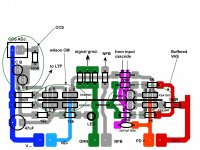
A question for KT ?? Why the npn beta enhancement trannies for the VAS. ?
Not to contradict the simulator , but the ampslab bi240 and Nico's ELD use rail referenced NPN devices. WHY?? one is a commercial kit and the ELD is a working
project. With added "garbage"(ac components) on the rails , various errata and reduced performance is the result (worse PSRR). Your present version works well as it is simulated , but the "typical" arrangement works over a wider range of LTP/VAS currents with more consistent THD and linearity. Some "rabbit holes" ..I will NOT go down. It was at 20khz and above where I encountered "glitches" , I could make them disappear by stepping to the right operating points.
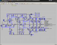
Below is what I am going to "put to board" (attachment 1 /2). It is closest to the ampslab Bi240 Power Amplifier by AmpsLab w/ a touch of ELD. Read the "built for speed" page ... High End Power Amps - AmpsLab In simulation , he is not lying !!! In fact , with the wilson CM , this amp is even faster.
To make mine absolutely
DIY "friendly" , a builder will be able to jumper out the input cascode (to use bjt's), the beta enhancement arrangement and have the choice of MJE340/350 or the KSA/C's. The Adjustable CCS (R6) , will accommodate either the 3mA+ FET or the 1.5ma BJT biasing.
I'm not going to wait , I'm just going to "do it" !!
OS
Not to contradict the simulator , but the ampslab bi240 and Nico's ELD use rail referenced NPN devices. WHY?? one is a commercial kit and the ELD is a working
project. With added "garbage"(ac components) on the rails , various errata and reduced performance is the result (worse PSRR). Your present version works well as it is simulated , but the "typical" arrangement works over a wider range of LTP/VAS currents with more consistent THD and linearity. Some "rabbit holes" ..I will NOT go down. It was at 20khz and above where I encountered "glitches" , I could make them disappear by stepping to the right operating points.
Below is what I am going to "put to board" (attachment 1 /2). It is closest to the ampslab Bi240 Power Amplifier by AmpsLab w/ a touch of ELD. Read the "built for speed" page ... High End Power Amps - AmpsLab In simulation , he is not lying !!! In fact , with the wilson CM , this amp is even faster.
To make mine absolutely
DIY "friendly" , a builder will be able to jumper out the input cascode (to use bjt's), the beta enhancement arrangement and have the choice of MJE340/350 or the KSA/C's. The Adjustable CCS (R6) , will accommodate either the 3mA+ FET or the 1.5ma BJT biasing.
I'm not going to wait , I'm just going to "do it" !!
OS
Attachments
Last edited:
I say again, a simulator is not the be all of electronics. Components in a simulation are perfect unless of course you have gone to the trouble of modelling each component you use to that of a practical real component, else your simulation is just that, a simulation. A good indication of how things could work theoretically.
Why don't you just let Kean choose the regulator rather than throw a rant in this thread that he has gone to the trouble of starting? He is doing good work as far as I see.
jam:
good point about the jumpers!
next in charlotte probably next year; i don't have enough vacation left to go again before then. i've already served notice that next trip, i'm spending time for "audio investigations"
i'll see you then. maybe by then, we can listen to this amp!
😉
mlloyd1
good point about the jumpers!
next in charlotte probably next year; i don't have enough vacation left to go again before then. i've already served notice that next trip, i'm spending time for "audio investigations"
i'll see you then. maybe by then, we can listen to this amp!
😉
mlloyd1
Hi Michael,
Yes I am ok with it but if for some reason I don't need drivers.........two jumpers will solve the problem.😉
You will also need drivers if you switch to a bipolar output stage.
So when will you be visiting Charlotte next?
Regards,
Jam
Nico, I asked what you meant by "derive impedance" and you never answered me. Without this, I can't possibly answer your questions intelligently. So any rant is moot, unless you're willing to accommodate my level of knowledge.
If you can find any fault with how I have graphed the impedance of my regulators, I'm all ears.
No, I had no MIT class to doze through. I'm a senior in high school! And I'm not an engineer! That's how it is!
OS, the reverse buffer was an experiment by me. In simulation they perform the same, except in PSRR, where yours is better. I concede victory. "glitches" shouldn't happen though. Can you elaborate?
I wanted to post some new stuff, but my mouse has an extreme multi-click problem, and I've run out of time.
One thing - I want to RC the drivers off the upper rails with 220R+22uF+10nF decoupling. This way, the VAS and LTP are protected from the driver currents. Thoughts?
- keantoken
Guys, in my short time between school and sleep, I have been hammering the keyboard and drove my mouse to insanity. I have not been as thorough in some responses as I would have liked. I have also made mistakes and found less favorable responses from folks I usually call my friends. While some of us like where the design is going, the other crowd is difficult to read.
Point is, really I have little experience except by proxy from other members of this forum. While the ideas I post I am reasonably sure of, they haven't been formally tested and may fall short in real life. I see little reason why they can fail based on other circuits I see that perform fine - however my vision is sometimes lacking.
As such, if you are encouraging me and like my circuits, be prepared if they turn out unworkable. If not, we should rely on the advice of more experienced members.
- keantoken
Keen , Not only do I value your input (and collect it ! ) , it "triggers" me to rethink my direction. 😎 Your reverse buffer actually has a plus that I incorporated into the "strait" one. Discussed in post #4 and #5 .. here : http://www.diyaudio.com/forums/solid-state/175934-comparison-vas-using-two-transistors.html
When you clip the standard configuration (mine) , it will "lock up" with unlimited base current available for the main VAS device. With your reverse buffer and my fix... (attachment 1 -R20/21 220R),
current is limited and the stage recovers from saturation. As a confirmation of the merit of this "fix" , ampslab also uses it in the Bi240 (it works).
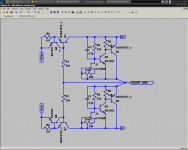
I am coming along with the actual voltage board (attachment 2) and will most likely have the real thing in november.
The drivers won't have a lot of current fluctuation .. nowhere as much as a BJT OPS , being biased into class A with the just the load of Re and the Cdg of the laterals. I guess it couldn't hurt, but would not the regulators take care of this ?? (see 3'rd pix)
OS
When you clip the standard configuration (mine) , it will "lock up" with unlimited base current available for the main VAS device. With your reverse buffer and my fix... (attachment 1 -R20/21 220R),
current is limited and the stage recovers from saturation. As a confirmation of the merit of this "fix" , ampslab also uses it in the Bi240 (it works).
I am coming along with the actual voltage board (attachment 2) and will most likely have the real thing in november.
One thing - I want to RC the drivers off the upper rails with 220R+22uF+10nF decoupling. This way, the VAS and LTP are protected from the driver currents. Thoughts?
The drivers won't have a lot of current fluctuation .. nowhere as much as a BJT OPS , being biased into class A with the just the load of Re and the Cdg of the laterals. I guess it couldn't hurt, but would not the regulators take care of this ?? (see 3'rd pix)
OS
Attachments
OS, FETs require more drive than BJT's at high frequencies. If this did not matter, we would not be designing a high-speed amp, and as such I feel compelled to protect the frontend against HF interaction. The regulator will help of course, but I designed it to improve regulation of the frontend, not to take up for where the driver decoupling is left lacking. BTW, the fastest regulator is a well-placed snubber.
One of the things I like about the reverse-buffer is that all the driving power is not focused in one direction. If the arrangement is driven hard, instead of transconductance/gain rapidly multiplying, either transistor will turn off and limit the gain. If the reverse buffer hasn't been tried before perhaps it is worth investigating? This compromise improves PSRR.
- keantoken
Attachments
OS, FETs require more drive than BJT's at high frequencies. If this did not matter, we would not be designing a high-speed amp, and as such I feel compelled to protect the frontend against HF interaction. The regulator will help of course, but I designed it to improve regulation of the frontend, not to take up for where the driver decoupling is left lacking. BTW, the fastest regulator is a well-placed snubber.
One of the things I like about the reverse-buffer is that all the driving power is not focused in one direction. If the arrangement is driven hard, instead of transconductance/gain rapidly multiplying, either transistor will turn off and limit the gain. If the reverse buffer hasn't been tried before perhaps it is worth investigating? This compromise improves PSRR.
- keantoken
Is it prudent to take this to Schematic layout in KiCad THEN on to a general PCB layout?
Before making a layout we need to determine which traces need to be shortest, which components need to be closest, etc.
1: Ground plane for decoupling.
2: Star ground, and another one for input ground, input resistors and 8.6p cap.
3: Input ground separated from circuit ground with 10R||diodes.
4: Don't connect signal path to ground plane.
5: Connect ground plane to ground at star ground, same for signal path grounds.
6: Connect driver decoupling near FET rail decoupling, to provide a non-convoluted path for FET Cj currents.
7: Shunt reg connects right at input LTP, then to VAS, then to drivers.
8: Combine shunt grounds where they connect with the circuit.
Do I have this right?
Here is the shunt schematic, borrowing Salas' SSHV input reference.
- keantoken
Attachments

What I was saying is what you are saying now. GENERAL layout of parts NO TRACES.
Overall objectives and features...
We are on the same page... I just did not convey my thoughts clearly enough...
Thanks
Overall objectives and features...
We are on the same page... I just did not convey my thoughts clearly enough...
Thanks
Make trimmer 500R, use K170GR grade for small pinch off, make the 100u 3u3. It will be charging a 100u forever to reach Vo, and suddenly during one random on cycle, it will kick back through the Jfet burning it plus collateral its shunt BJTs.
Make trimmer 500R, use GR grade, make the 100u 3u3. It will be charging a 100u forever to reach Vo, and suddenly it will kick back through the Jfet burning it plus collateral its shunt BJTs.
Should the 3u3 be polarized or not. I am assuming YES.
Of course if its gonna be a lytic and you don't wanna spend $ and bulk on a Vishay or Wima MKP (which is very influential there).
- Home
- Amplifiers
- Solid State
- Goldmund Mods, Improvements, Stability