I have an original copy of Henrik Bode's book, I think 1949 issue. If you think about it for a minute, we are so privileged that we can look up anything we want. So easy, in fact, that often we are to lazy to bother, and are content with parroting whatever we hear or read, whether it is BS or not.
These guys had to invent it step by step, groping around for clues.
Fascinating.
Trivia: when the US Navy put electric drive on their battleship guns to slew them around faster to be able to kill those zeros, they found it didn't work as they thought! The guns slewed, then overshot, turned back, overshot THAT and started to oscillate wildly. Then they increased the gain in an attempt to stop it, and the guns actually destroyed their mountings. That's when some smart guys like Bode started to really think hard about what the f*ck was going on.
And the rest, as they say, is history.
As I said, fascinating!
Jan
Last edited:
An ex told me about homeostasis, or, as she eloquently put it, "If you are eating sleeping and shiting regularly, there's f*** all wrong with you"
I will have to call my next dog Ma, so there will be at last one in this house.
IIRC Ma is horse in Chinese.
Look at the old NE5534. Its open loop -3 dB frequency is 10 kHz. This pretty much avoids the whole issue.
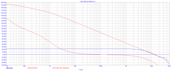
This remains a total mis-conception, you can apply a very small amount of positive feedback to the null pins on many op-amps to give them an arbitrarily low open-loop gain corner and it make no difference at all to the distortion performance at high frequencies.
You are still in the Land of the Linear.In fact, in this example, the top one, smaller OL bandwidth amp, has either more or the same distortion reduction than the lower, wide bandwidth one.
Jan

This remains a total mis-conception, you can apply a very small amount of positive feedback to the null pins on many op-amps to give them an arbitrarily low open-loop gain corner and it make no difference at all to the distortion performance at high frequencies.
I don't know if it's a misconception, but I am aware of the technique you're talking about. But I think you want to raise the open loop gain corner. 😉
You can compensate for higher closed loop gain and apply feedforward compensation to the feedback loop too. And you can slow the amplifier down and apply a large amount of negative feedback so the loop gain in the audio band is very high. It's all a juggling act.
Oh, that evil feedback.

bucky bunny,
you might be the right man to answer this question. How many zeros after the decimal point should a good sounding amplifier churn out? Unlike physical processes, distortion figures are easy to interpret.
Now, how to get more zeros? Well, by way of more feedback, which is a research and evidence-based fact, not my weird opinion.
More feedback to the people.
We are back to square one. I am trying to clean up my tarnished reputation. Any upvotes?
One more than your loudspeaker.How many zeros after the decimal point should a good sounding amplifier churn out?
loudspeaker means one that's speaking loud...can you hear someone that's speaking 10 times softer than you? I think that you can! Then speaker's distortions aren't the same type as amplifier's distortions...No speaker distortion will be in phase or identical in shape with its amplifier so again...the amp's distortion will add to the speaker's one.If a smal bird is squeaking next to a lion roaring i think that you can hear the bird too...You may not notice the bird until your ear adjust with the roar level, but our hearing is smart enough due to millions of years of evolution in the wild with no weapon at hand!One more than your loudspeaker.
Last edited:
How many speaker designers are there here? It's a different ball game to assembling an amplifier from available components.Then speaker's distortions aren't the same type as amplifier's distortions..
I wonder if one reason for any perceived sound degradation as a result of GNFB is that a typical amplifier will have a very low signal level at the VAS input. In fact, the higher the VAS gain, the lower the signal level. Since the input-referred noise at the VAS input doesn't change with VAS gain, the SNR will be quite low. For example, at 2.83V output (1W into 8 ohms), a VAS with 80dB gain will have an input signal of only 283 uV. Of course GNFB will "correct" this noise and the math eventually "works out" but this does make me somewhat uneasy. A lot of musical detail will be a at levels much below 283 uV, possibly below the noise floor. I am unable to confirm losing this detail through simulation (by putting a noise voltage in series with the VAS input) but this is only a simulation and may not actually represent what really happens in real devices. At the very least, it would give people who define an amplifier's resolution based on it's noise level something to think about.
Another consequence of high VAS gain is potentially more susceptibility to demodulating RF noise into the audio band. I actually confirmed this with simulation. Inject a 1000k+1010k signal into the VAS input circuit and look at the first order IMD product at 10k. By decreasing VAS gain by 20dB and increasing IPS gain by 20dB (thus keeping overall loop gain constant at 60 dB) the IMD dropped by a whopping 40 dB. Interestingly, at least in my simulated amp at least, the overall distortion profile did not change.
Those guys hanging load resistors on the VAS output might be onto something after all. Seems to me this hypothesis would be easy to test. An amp with an LTP loaded with a current mirror, and a degenerated cascoded VAS would be an ideal candidate to test which way it sounds better, or if it's the same.
283µV? This is lower than some level from some MC cartridges... and we need to care a lot about noises (intrinsic and external) at this levels
Try to use an ordinary transistor that we use routinely on VAS stages in MC preamps, and see the poor noise level that results.
Some time ago, prototyping a germanium transistor preamp (generally more noisier than Si couterparts), I noted the importance for total noise floor, the VAS transistor needs to be the LOWEST noise one, if input is at "normal" levels (~100mV input), since the VAS will manipulate the lowest amplitude from all stages here (my testing are on a very ordinary 2 transistor pre, for a friend, for guitar).
Probably this rule is good to follow in more common 3 stage feedbak amps too.
Of course, one can analyze the bipolar VAS at current levels, and not voltage, but then we need to experiment changing the bipolar VAS for a MOS one, for instance, and see that this low signal amplitude influentiate.
Maybe this VAS SNR related issue is one from easy explanation, but I don't know this explanation, or forget, or both... 😉
I wonder if one reason for any perceived sound degradation as a result of GNFB is that a typical amplifier will have a very low signal level at the VAS input. In fact, the higher the VAS gain, the lower the signal level. Since the input-referred noise at the VAS input doesn't change with VAS gain, the SNR will be quite low. For example, at 2.83V output (1W into 8 ohms), a VAS with 80dB gain will have an input signal of only 283 uV. Of course GNFB will "correct" this noise and the math eventually "works out" but this does make me somewhat uneasy. A lot of musical detail will be a at levels much below 283 uV, possibly below the noise floor. I am unable to confirm losing this detail through simulation (by putting a noise voltage in series with the VAS input) but this is only a simulation and may not actually represent what really happens in real devices. At the very least, it would give people who define an amplifier's resolution based on it's noise level something to think about.
Another consequence of high VAS gain is potentially more susceptibility to demodulating RF noise into the audio band. I actually confirmed this with simulation. Inject a 1000k+1010k signal into the VAS input circuit and look at the first order IMD product at 10k. By decreasing VAS gain by 20dB and increasing IPS gain by 20dB (thus keeping overall loop gain constant at 60 dB) the IMD dropped by a whopping 40 dB. Interestingly, at least in my simulated amp at least, the overall distortion profile did not change.
Those guys hanging load resistors on the VAS output might be onto something after all. Seems to me this hypothesis would be easy to test. An amp with an LTP loaded with a current mirror, and a degenerated cascoded VAS would be an ideal candidate to test which way it sounds better, or if it's the same.
Finally something interesting. I've been experimenting with some circuit lately and loading the VAS with particular value resistor, lowered the 2nd harmonic quite a bit...
And how much you need to strengthen with the help of an open General OOS . 80 dB? 100 dB or 130 dB at a frequency of 20 kHz ?so good or little gain ?
Attachments
Last edited:
I think that will depend on the design. If you are using a diamond quad (and can make it work) you can probably get away with 50 dB loop gain or so at 20 kHz and still have distortion under 0.001% at 20 kHz. Both the IPS and VAS can be built with local feedback in which case you won't need a huge amount of loop gain, 50 to 60 dB will suffice. With triple output, you're looking at a 20 dB increase in output stage switching distortion, at least in my sims.
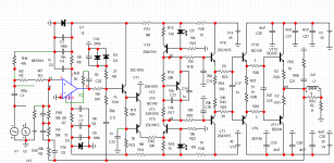
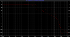
Here is the CCIF 19+20k IMD at 80 Vpp into 4 ohms, and loop gain plot. I cut off the IPS from the amp image since it is based on Figure 7.13 in Bob Cordell's book, not sure if I'm allowed to post it here.
Attachments


- Home
- Amplifiers
- Solid State
- Global Feedback - A huge benefit for audio