Okay, I rebuilt it with some 2N396s and 2N1303s and 2N1304s. The 1303s are for Q2, and I knocked off the first stage which looked just like a buffer. Is that right? My iPod (my main input for headphone enjoyment) can drive it just fine by feeding directly into Q2.
I'll post pictures later, but the square wave response in my opinion is amazing!! At 100KHz, they still seem to look great!! The high end frequency response is obviously quite good. The low end could use some improvement, so I think I'll replace my 47uF caps on the input with 100uFs or larger.
Mooly, all I can say is the design is amazing and I couldn't be any more happy with it! Thank you very much for your help and sharing the circuit!!
Kyle
The first stage technically isn't needed... it actually attenuates slightly with the values shown... but seems to add it's own magic to the subjective sound quality (I hate saying that... but it's true) probably by adding second harmonic distortion in very small quantities.
Pleased you like it... it was all about building something that sounded amazing rather than absolute technical perfection... and how it sounds is what it's all about.
Pleased you like it... it was all about building something that sounded amazing rather than absolute technical perfection... and how it sounds is what it's all about.
Member
Joined 2009
Paid Member
My OC71's haven't arrived yet but I'm keeping an eye out for them - not sure what to do with them yet but Mooly's amp will be the inspiration 🙂
Anybody able to volunteer me a spice model for them ? (I know Mooly won't have one !)
Anybody able to volunteer me a spice model for them ? (I know Mooly won't have one !)
Member
Joined 2009
Paid Member
They haven't arrived because I forgot to update my address on eBay - the package was returned to sender. I may never see them now....
Member
Joined 2009
Paid Member
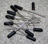
Ahhh, the old red spot transistors... rf devices had a white spot for the collector you know.
Not a lot of people know that
Have fun.
Not a lot of people know that
Have fun.
Member
Joined 2009
Paid Member
Not a lot of people know that
A Michael Cain fan ? (I remember this being one of his catch phrases)
Well, the red-dot black LEDs are now on my shelf and when something perculates to the surface I'll have to have a go at devising something that makes use of them - inspired by Mooly....
Finally etched a PCB (amp only). I found some old russian germanium NPN transistors, MP37b and MP38a, will try them for Q6.
High end germanium headphone amplifier.
.
.
Attachments
Last edited:
A more clear pcb?
Dear friends,
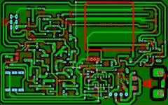
I am writing from Turkey. I have gone over the PCB file proposed and did minor changes (namely less wire links.), and writing the component values on the parts so it would be easier to place them.. and has a more professional look 😉. I added Sprint Layout file for this PCB. I use Sprint Layout to replicate proposed pcb files in jpg format 😉 It is kind of cheating but when you are desperate...
Attached file contains both the layout file and XPS files for toner transfer. If you wish you can change the tracks etc if you can design it better.
Did I test it? NO. (I just followed the schematics for part values so CHECK them if you'll use this PCB)
Do I even have required germaniums? NO
I did it just for the sake of old times and people who are lucky enough to have these Germaniums.
Please check this and return if any errors you find and /or mods you want.
Dear friends,
I am writing from Turkey. I have gone over the PCB file proposed and did minor changes (namely less wire links.), and writing the component values on the parts so it would be easier to place them.. and has a more professional look 😉. I added Sprint Layout file for this PCB. I use Sprint Layout to replicate proposed pcb files in jpg format 😉 It is kind of cheating but when you are desperate...
Attached file contains both the layout file and XPS files for toner transfer. If you wish you can change the tracks etc if you can design it better.
Did I test it? NO. (I just followed the schematics for part values so CHECK them if you'll use this PCB)
Do I even have required germaniums? NO
I did it just for the sake of old times and people who are lucky enough to have these Germaniums.
Please check this and return if any errors you find and /or mods you want.
Attachments

Nice work 🙂
(It would easily translate into silicon with only minor changes to some component values for anyone wanting to build it).
(It would easily translate into silicon with only minor changes to some component values for anyone wanting to build it).
Hi Mooly,
Just discovered your exploration of germanium transistors in your headphone amp design.
I've been making small amps and especially headphone amps since I was a kid and was always surprised at the loss in sound quality when I used silicon transistors in place of germanium ones. For me Ge has a more interesting and full sound that has more in common with tubes than Si which generally tends towards sibilance. The frequency response between the two technologies in my headphone amp is very similar so perhaps its a harmonic distortion difference. I've not measured it that way. All I've done is listen to the different transistors and selected the ones I like best. My headphone amp is also class A and uses a hybrid Ge-Si output stage as the BD140 silicon output transistor seems to work better at higher current than the even older Ge output transistors. I suspect Ge is better at medium-level circuitry like line stages and headphone amps rather than high power in poweramps and low noise phono and microphone circuits. Although I did build a Ge MC stepup with paralleled MP38s that was a touch noisy but sounded characterful and satisfying.
Sounds like you have been having fun.
I must admit I didn't try a Si version for comparison as I had enough quantity of the germaniums and wanted to use them. As you seem to have found, the results proved worth the effort.
I must admit I didn't try a Si version for comparison as I had enough quantity of the germaniums and wanted to use them. As you seem to have found, the results proved worth the effort.
They seem to be available from the usual suspects. Beware of AFxxx types that may well be suffering from this problem:
https://nepp.nasa.gov/whisker/anecdote/af114-transistor/2005-Brusse-tin-whiskers-AF114-transistors.pdf
https://nepp.nasa.gov/whisker/anecdote/af114-transistor/2005-Brusse-tin-whiskers-AF114-transistors.pdf
- Home
- Amplifiers
- Headphone Systems
- GERMANIUM Single ended Class A Headphone Amp.