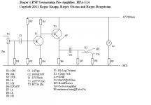
Hello. It is necessary to adjust R15 so that at points E and FHello,
Tell me "vsmusic", how to set-up the variable resistor R15, in the Victoria pramplifier ?
In the 70s, some auto-radios from Philips were manufactured in France, at Dreux.
I did an internship with them at that time.
 were the voltage shown in the diagram
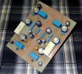
I know this is an old thread, but I thought we could keep it going.
Friend of mine gave me vintage portable reel to reel player, beyond repair. I salvaged germanium transistors out of the board. 2SB170 and 2SB172.
Any simple schematics for buffer or line level preamp?
I see some already, but if someone has personal experience, even better.
Friend of mine gave me vintage portable reel to reel player, beyond repair. I salvaged germanium transistors out of the board. 2SB170 and 2SB172.
Any simple schematics for buffer or line level preamp?
I see some already, but if someone has personal experience, even better.
thanks vsmusic, that looks impressive
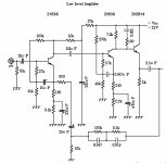
i will start easy, with single stage
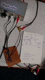
here is what i built on test board
its single stage preamp, with 2sb170
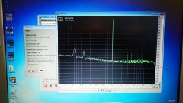
it performs admirably, distortion is 0.071%, intermodulation 0.112%
yes, I have some power supply hum, you can see 60 and 120Hz residual, i will work on that
i will be building buffer next, likely first stage from the schematics you posted, thanks
i will start easy, with single stage
here is what i built on test board
its single stage preamp, with 2sb170
it performs admirably, distortion is 0.071%, intermodulation 0.112%
yes, I have some power supply hum, you can see 60 and 120Hz residual, i will work on that
i will be building buffer next, likely first stage from the schematics you posted, thanks
Attachments
Last edited:
Eight years ago, a guy from Japan decided to make a preamp for himself . He used the 520 scheme . Unfortunately, the link to his project no longer works . He made only the Phono and the linear part . Without a tone control . He used the original transistors , as in the diagram of the JBL ......I made for myself only a phonopreamp from this scheme - my board is shown in the photo in message 202 . Work perfectly .
Attachments
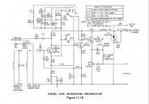

This is wrong . The level controller must be separated by a capacitor . If there is a DC-voltage on the level controller, it will make noise during adjustments ...There must be a capacitor in front of the level controller
Last edited:
I just did that buffer, with no volume control. It works fine, sounds good, little lower distortion that preamp. It measures ~0.066% distortion with RightMark Audio Analyzer (using crappy old laptop).
I think I will make one more buffer. Then I will use preamp (with volume control on the input, I already did that) first, then split the signal into high path (150Hz up) and low path (150Hz and lower) using just PLLC, and add those two buffers on the output. It should work as buffered passive line level crossover. Will see how it sounds.
I think I will make one more buffer. Then I will use preamp (with volume control on the input, I already did that) first, then split the signal into high path (150Hz up) and low path (150Hz and lower) using just PLLC, and add those two buffers on the output. It should work as buffered passive line level crossover. Will see how it sounds.
JBL-SG520

Thanks for reply
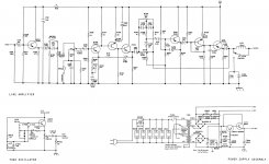
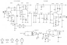
Hi everyone, I want to copy JBL-SG520, just need its audio amplifier circuit, JBL SG520 has many unnecessary circuits, such as tone control, filter and tone oscillation circuit for gain adjustment, so I cut it off completely. Is this circuit diagram correct? I searched the network but couldn't find the 25uf capacitor in the picture.oh,my god.....
Thanks for reply
Yes - this circuit diagram correct .Hi everyone, I want to copy JBL-SG520, just need its audio amplifier circuit, JBL SG520 has many unnecessary circuits, such as tone control, filter and tone oscillation circuit for gain adjustment, so I cut it off completely. Is this circuit diagram correct? I searched the network but couldn't find the 25uf capacitor in the picture.View attachment 903225
Thanks for reply
Attachments
Yes - this circuit diagram correct .
The original circuit diagram is 25mf
- Home
- Amplifiers
- Solid State
- germanium Preamp?