Old thread Germanium triodes investigations Hockey Puck SIT 2SK180 by Tokin source NOS Have a nice day
Is it ГT404 or ГT403?
ГT403 have more power than ГT402 and ГT403 has no complementary pair.
Attachments
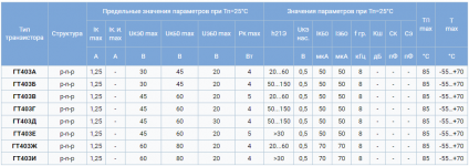
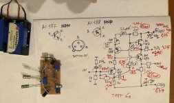
Analog: AC187 - ГТ404Б, AC188 - ГТ402Е.
There is information on analogs here.
?????????? ???????? ????????? ???????????? ?? A..
There is information on analogs here.
?????????? ???????? ????????? ???????????? ?? A..
I bought the last 16 pieces of 1T813. New, from one batch. Maybe they won't be on sale anymore.
I got about 100-150 GE PNP TO3 transistors.Mostly AD149 and ASZ series. But also about a dozen 2N555
Now Ive only ever done a P3A amp to replace a guitair amp for someone.
Is there any point in making an amplifier out of these? Just for fun. I can imagine i need to figure something out to avoid thermal runaway.
I got some MAT02's that could serve as the differential front end.
I can do board design just fine, im just wondering if there is anything worthwile to build with these.
I put together one simple buffer circuit last evening
But with Germanium AC187 AC188
.
The Kuartlotron - keantoken's simple error-correction superbuffer
.
It was very good sounding. 🙂
More on the link, just one photo.
But with Germanium AC187 AC188
.
The Kuartlotron - keantoken's simple error-correction superbuffer
.
It was very good sounding. 🙂
More on the link, just one photo.
Attachments
Hi 🙂
With "little" delay I tried Germanium version of this buffer.
And it was OMG sound last evening...
Circuit working with Ge devices AC187 and AC188.
For the test I not solder unmark parts, RC input filter, choke 2.2uH.
Capacitors at the PS are ommited too because I power device from the 2x9V battery pack.
Rest 2 capacitors was 10uF (against 470uF in the original sch.)
.
-It was possibile to set 1/2 +V at the test point.
-I just set another pot to 56ohms didnt measure and eventualy correct dist yet.
-off set is about -40mV with (I think) pot of 2M full value. Initialy was -52mV and with inreasig value droped.
-Transistors randomly picked.
-No overheating, 1st pair are consume about 4mA second pair is about 8.5mA.
-Second pair just slightly warm. First pair are cold.
-Circuit not showing any hum or his. Very silent.
I tried with Quad II power amplifier and with transformer input Western Electric Germanium amplifier.
.
The sound was vey good. Natural and with "body". Digital media are somehow moved to analog sound and made ballans with start-finish of the tone. Not to emhesize the finishing HF end. Circuit with Ge somehow "reduce" digital "signature". Instruments are neutral and transpraent, echoes are clear and also with fundament. Bass is very good.
But the voices are beautiful 🙂
.
I just listen one channel last evening until I the batteries are almost drained 🙂
Bravo Zoran! Thanks for sharing 🙂
Your sound descriptions match a lot my audio experiences with germaniums.
Want try more
Thanks
I am very satisified with this circuit. And I will try some more options. I prommise Kean (from the buffer topic) long time ago to try his concept but with Ge devices. Now this topic was catalist to seed up the simple test circuit...
With the battery power performing well in terms of hum but maybe it will be not good with classic power supply. We will see...
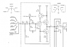
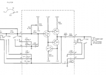
Interesting somehow similar aproach had Oliver Barney in
http://www.hparchive.com/Manuals/Barney_Oliver_Amplifier_Manual.pdf
with silicon devices line stages. I think that these can be transcribed to Ge parts too.
http://www.hparchive.com/Manuals/Barney_Oliver_Amplifier_Manual.pdf
with silicon devices line stages. I think that these can be transcribed to Ge parts too.
Attachments
I remember that EMT had unit NoisEx. At the output have stage with AC187/88. That module drive output intersage transformer. And power supply with some Ge transistors too. I have the schematic form original PCB scetched and I will post latter...
Zoran, could you please take some measurements? Even bandwidth alone would be interesting.
From what i remember GE circuits had mostly issues with bias/temperature stability even at moderate currents, so biasing arrangements were always more complicated. DC coupling is clearly going to be problematic. How does you buffer respond to heat?
From what i remember GE circuits had mostly issues with bias/temperature stability even at moderate currents, so biasing arrangements were always more complicated. DC coupling is clearly going to be problematic. How does you buffer respond to heat?
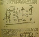
Precursor circuit JlH1969 in an Italian magazine 1967 p.930. Class AB (version on Ge) is made on transistors of the same conductivity.
http://www.introni.it/pdf/Costruire diverte 1967_12.pdf
http://www.introni.it/pdf/Costruire diverte 1967_12.pdf
Yes I will measure buffer alone and post.
.
As I spot from touching pairs they should be thermaly coupled (but they not at the test version) it seems that points are stable. But power supply was from the batteries and little undervoltage.I is qiwstion how it eill be with a hum and other things with classic PS...
.
I have to test max input signal before clipping and probaly will try to rise up PS supply voltages to +-12 or +-15V. Because now transistors opperate about half PS voltages of 4-5V Vb. I think (I am far from expert) that is a bit low for line level P-P signals.
.
I tried sonicaly after Apple MBP headphone output With/Without Buffer, and it was clear that the sound is much much better.
second try was at the end of DAC followed with passive filter and buffer again it was better than simpiest version of JFET buffer.
.
[Rest of the chain was 2 aplifiers tested each Quad II tube amp and WE germanium amp. Speaker was some Saba saled cab with Philips FR driver. double cone (not alnico) inside. Worst case scenario space, no carpet, glass ewerywhere total 12m2 glass surface, more than half empty...]
.
As I spot from touching pairs they should be thermaly coupled (but they not at the test version) it seems that points are stable. But power supply was from the batteries and little undervoltage.I is qiwstion how it eill be with a hum and other things with classic PS...
.
I have to test max input signal before clipping and probaly will try to rise up PS supply voltages to +-12 or +-15V. Because now transistors opperate about half PS voltages of 4-5V Vb. I think (I am far from expert) that is a bit low for line level P-P signals.
.
I tried sonicaly after Apple MBP headphone output With/Without Buffer, and it was clear that the sound is much much better.
second try was at the end of DAC followed with passive filter and buffer again it was better than simpiest version of JFET buffer.
.
[Rest of the chain was 2 aplifiers tested each Quad II tube amp and WE germanium amp. Speaker was some Saba saled cab with Philips FR driver. double cone (not alnico) inside. Worst case scenario space, no carpet, glass ewerywhere total 12m2 glass surface, more than half empty...]
Great thanks for documents about Ge amplification circuits.
Some of the public domain old books is not longer available on line
but the other happyly are , from the 50's good old days
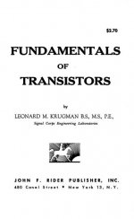
Krugman_-_Fundamentals_of_Transistors_1954 : Free Download, Borrow, and Streaming : Internet Archive
include chapters about how to test transistors , different bias circuits solutions, class A amplification topologies etc.
Let's investigate Ge Have a nice Sunday
direct link for download https://ia803108.us.archive.org/29/...rugman_-_Fundamentals_of_Transistors_1954.pdf
Some of the public domain old books is not longer available on line
but the other happyly are , from the 50's good old days
Krugman_-_Fundamentals_of_Transistors_1954 : Free Download, Borrow, and Streaming : Internet Archive
include chapters about how to test transistors , different bias circuits solutions, class A amplification topologies etc.
Let's investigate Ge
Have a nice Sundaydirect link for download https://ia803108.us.archive.org/29/...rugman_-_Fundamentals_of_Transistors_1954.pdf
Attachments

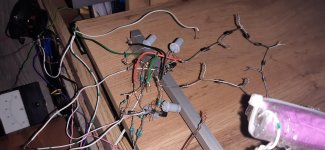
Today I p2p aseembled "JLH Buffer" with 2SK246/2SJ103 and GT402ZH/GT404ZH.
No matching. First channel had 38mV output DC with no load. Tested with earphone, it's working. Then I measured the other one, which was -132mV output DC, so I added 220R resistor in parallel to existing 220R, and voila, both of them have 38mV DC out. As I am using these to drive another capacitor coupled stage, I won't attempt to get lower DC. Soundwise, I cannot tell yet the difference from Mosfet source follower I used in exact link of soundchain, because I cannot fully enjoy it at the moment (not a good time for it). I predict it to be different sound than mosfet follie tho. I'll hear later.
And those resistors were a tad toasted, but I could't find another ones, sorry.
Attachments

- Home
- Amplifiers
- Pass Labs
- Germanium investigations