Dear Paul W,
quite a shame U did not keep some measurements for this most interesting ribbon experiment of yours.
Is it a Bohlænder Græbener ribbon? Or something of unknown maybe 'home made' manufacture?
Kind regards
Sven R. Olsen
quite a shame U did not keep some measurements for this most interesting ribbon experiment of yours.
Is it a Bohlænder Græbener ribbon? Or something of unknown maybe 'home made' manufacture?
Kind regards
Sven R. Olsen
Last edited:
Member
Joined 2003
GD,
It was a DIY ribbon. Here is a similar ribbon but without WG.
1"x45" ribbon, no EQ
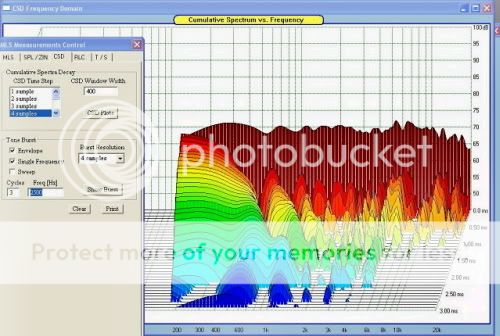
Since it didn't have WG, I don't want to clutter Earl's thread too much.
Paul
It was a DIY ribbon. Here is a similar ribbon but without WG.
1"x45" ribbon, no EQ
Since it didn't have WG, I don't want to clutter Earl's thread too much.
Paul
Hi Paul,
if Ur own ribbon worked in the same fashion I can only join the exclamations and say: good work!
I do however seem to spot some possible 'grid or edge' diffractions in the mid to high mid? But the damping the waterfall shows to be remarkable.
Is there (or where) another thread where this is covered, since I aggree not to disturb Dr. Geddes unduly.
Regards
a1greatdane
Dr Geddes wrote said:Ribbons have some advantages, but a lot of drawbacks, mostly efficiency. They also tend to be fairly unreliable. Thats why you never see them in Pro.
http://www.alconsaudio.com/site/technology.html
You might have missed this. Not available in the USA at the moment, and only in their finished product.
Iain.
UK
I dont know
A pair of 1.2meter x 2" diy planar/ribbon is easily built and cost around 200USD in magnets
Båndseis new ones sound terrific, and you go home thinking "I really need to have a pair"
A pair of 1.2meter x 2" diy planar/ribbon is easily built and cost around 200USD in magnets
Båndseis new ones sound terrific, and you go home thinking "I really need to have a pair"
alcons audio - evolutionary audio solutions ®
You might have missed this. Not available in the USA at the moment, and only in their finished product.
Iain.
UK
The thing is, beyond what I said before, ribbons are the wrong shape for good directivity control - they are very hard to do a good waveguide for. And, as I said, the bottom line is that they end up working like a compression driver. I've know lots of people who try them, but nobody who has stayed with them. Theoretically I just don't see an advantage.
I actually have one design in the works using a driver that is called a ribbon, but is actually a modal radiator type.The thing is, beyond what I said before, ribbons are the wrong shape for good directivity control - they are very hard to do a good waveguide for. And, as I said, the bottom line is that they end up working like a compression driver. I've know lots of people who try them, but nobody who has stayed with them. Theoretically I just don't see an advantage.
Minimum horn mouth diameter is restricted to:
Dmin = 4c/2*pi*fmin
and we can't do any tweak? For example to reach 200Hz we need 4*342/6,28*200 = 1 meter mouth?
Dmin = 4c/2*pi*fmin
and we can't do any tweak? For example to reach 200Hz we need 4*342/6,28*200 = 1 meter mouth?
Minimum horn mouth diameter is restricted to:
Dmin = 4c/2*pi*fmin
and we can't do any tweak? For example to reach 200Hz we need 4*342/6,28*200 = 1 meter mouth?
If you are looking for a simple answer, yes, that's correct. If you want a more detailed answer you have to model it. Usually the simple answers are only "sometimes" correct.
Ok we modeled Gaussian waveguides and with 1 meter mouth we've got 900Hz. Pretty high. Another equation for optimal throat area:
Rg - source resistance
Re - vc resistance
ro - air density (?)
Sm - membrane area
Bl - force factor
This means that membrane, suspension and rear chamber resonance must be at the middle of a horn bandwidth and Qtc low so that load resistance and (Bl)^2/(Rg+Re) as high as possible. That's old teaching right?
Code:
S = ((Rg+Re)*(ro*c*Sm^2))/(Bl)^2Rg - source resistance
Re - vc resistance
ro - air density (?)
Sm - membrane area
Bl - force factor
This means that membrane, suspension and rear chamber resonance must be at the middle of a horn bandwidth and Qtc low so that load resistance and (Bl)^2/(Rg+Re) as high as possible. That's old teaching right?
Last edited:
Ok we modeled Gaussian waveguides and with 1 meter mouth we've got 900Hz. Pretty high. Another equation for optimal throat area:
Code:S = ((Rg+Re)*(ro*c*Sm^2))/(Bl)^2
Rg - source resistance
Re - vc resistance
ro - air density (?)
Sm - membrane area
Bl - force factor
This means that membrane, suspension and rear chamber resonance must be at the middle of a horn bandwidth and Qtc low so that load resistance and (Bl)^2/(Rg+Re) as high as possible. That's old teaching right?
I think thats based on optimal impedance matching for maximum power transfer. Thats not how I would define "optimum".
I know impedance is unimportant for you but do I understand this equation correctly? It tells throat area is larger than membrane area which is never a case 🙄
I know impedance is unimportant for you but do I understand this equation correctly? It tells throat area is larger than membrane area which is never a case 🙄
I don't know the assumption behind this equation, but the diaphragm area is not even mentioned.
Isn't that "Sm - membrane area"?I don't know the assumption behind this equation, but the diaphragm area is not even mentioned.

Isn't that "Sm - membrane area"?
Yes, my mistake. Not all combinations of variables will lead to a throat area > diaphragm area. At any rate, equations like that and lumped paramter approachs for waveguides arn't going to be very useful or very accurate.
Earl, what do you mean by centroid location in:
Compression driver plug - Google Patent Search
0.199/0.345/0.446/0.528
it doesn't lead to the picture. What is missing?
Compression driver plug - Google Patent Search
0.199/0.345/0.446/0.528
it doesn't lead to the picture. What is missing?
Earl, what do you mean by centroid location in:
Compression driver plug - Google Patent Search
0.199/0.345/0.446/0.528
it doesn't lead to the picture. What is missing?
I believe that the picture is correct. The centroid, is a fancy word for the center, but not necessarily the geometrical center (as seen in some view), but in this case is the center as defined by splitting an area. For example when you find the centroid of an annulus, it is NOT the physical center of the two radi. If you don't understand that then you need to brush up on your geometry.
- Home
- Loudspeakers
- Multi-Way
- Geddes on Waveguides