Wow - lots of progress around here!
RCW what are the scalings (dB per color / frequency range / horn dimension)?
If you export from AxiDriver there is also PNG you can choose. This is by far better for such plots compared to JPG format.
RCW what are the scalings (dB per color / frequency range / horn dimension)?
If you export from AxiDriver there is also PNG you can choose. This is by far better for such plots compared to JPG format.
This is an Axidriver simulation.
The mouth is 150mm. across and the device is specifically intended to be used with a nominally ten inch driver, with a crossover in the 1.5kHz. Region.
The sonogram has a total 45db. Range and that in the posted one has an overall 24db. Range from the darkest red to the light green.
As to the effect of the centre plug.
The overall driver has the property that the section to where it attaches to the throat produces a very good resemblance to a plane wave, and has the acoustic impedance of a Helmholtz resonator, (I am still preparing the various plots of this), that has close to a conjugate match to the horn impedance.
The Le Cleche style of horn has a very resistive impedance above cut off anyway so this is not of much importance in this case. As far as I am aware it would have no influence, and the whole thing would just act as an ordinary compression driver from that point of view.
Rcw.
Here is a comparisson of the horn driven by a flat piston and driven by the annular comp. driver..
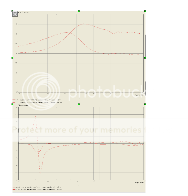
The top plot is the piston, the lower curve is the reactive part of the impedance.
rcw
The top plot is the piston, the lower curve is the reactive part of the impedance.
rcw
Hallo chaps and hopefully also some chappetes,
read a bit here with great interest and thought I would have the audacity to upload a response for a modified Radian driver, for everybody's hopefully kind perusal.🙂
It's a 1" exit device with 1.75" Radian proprietary 2mils special aluminium diaphragm and Mylar surround with an as close as I was able get it correctly implemented Bob Smith 3 concentric slits phase plug. Measurement is made on one of my proprietary small ConRadTM horn-flares with 1W@1m aligned.
Best regards
Sven R. Olsen
Creator
CSW-Chilli Sound Works
London N4, UK
read a bit here with great interest and thought I would have the audacity to upload a response for a modified Radian driver, for everybody's hopefully kind perusal.🙂
It's a 1" exit device with 1.75" Radian proprietary 2mils special aluminium diaphragm and Mylar surround with an as close as I was able get it correctly implemented Bob Smith 3 concentric slits phase plug. Measurement is made on one of my proprietary small ConRadTM horn-flares with 1W@1m aligned.
An externally hosted image should be here but it was not working when we last tested it.
Best regards
Sven R. Olsen
Creator
CSW-Chilli Sound Works
London N4, UK
... a modified Radian driver
It's a 1" exit device with 1.75" Radian proprietary 2mils special aluminium diaphragm and Mylar surround with an as close as I was able get it correctly implemented Bob Smith 3 concentric slits phase plug.
Best regards
Sven R. Olsen
Creator
CSW-Chilli Sound Works
London N4, UK
So the diaphragm is yours but the motor is Radian?
Some years ago I did a patent application wherein I showed how the Bob Smith approach to a phase plug was not really what one wants to do. You might want to look that up and read it.
Dear panomiac,
tnx for the nice (I take it?) approval.
Dear Dr Geddes,
No and no I'm afraid. It's sort of the other way around IE. it's a modified Radian Diaphragm, but this is 'sat on', a completely 'innom house' the CSW-Chilli Sound Works research, designed and manufactured piece of 'Hardware', incl. using some kindly by Radian supplied standard part's from their exiting 1" range. The main difference is that the phase plug is manufactured as closely as I'm able to do a 3 slit Bob Smith design. There is scope for possible more improvement mainly in the moving assembly/'software' department, but this would require some, at the present time fairly scarce, resource allocations.
Sincere regards
Sven R. Olsen
Creator
CSW-Chilli Sound Works
Interim working formerly Cluinn Ltd. (due for upgrade this winter) homepage at:
www.geocities.com/blueluti
Dear panomiac,
tnx for the nice (I take it?) approval.
Approval, absolutely! That's a nice plot for any horn, that you got it out of a Radian is even more laudable.
Dear Dr Geddes,
I feel with the best and non-prejudicial intentions obligated to take up on your kind offer and to my best humble abilities read, try to digest and comprehend Your suggested article/paper/patent application. A possible link to an address would in this connection be helpful and most appreciated. Otherwise I would be delighted to receive a copy by post. Please let me know possible cost implications and potential need for forwarded postal address.
Are You by the way familiar with the (mainly FEA) work done by Mark Dodd at Celestion/KEF?
He has given quite a number of papers at the AES and other Acoustic related societies.
Kind regards
Sven R. Olsen
Last edited:
Dear Dr Geddes,
I feel with the best and non-prejudicial intentions obligated to take up on your kind offer and to my best humble abilities read, try to digest and comprehend Your suggested article/paper/patent application. A possible link to an address would in this connection be helpful and most appreciated. Otherwise I would be delighted to receive a copy by post. Please let me know possible cost implications and potential need for forwarded postal address.
Are You by the way familiar with the (mainly FEA) work done by Mark Dodd at Celestion/KEF?
He has given quite a number of papers at the AES and other Acoustic related societies.
Kind regards
Sven R. Olsen
Yes, I've read Mark Dodds work.
In the US it's easy to get the patent application. Just goto USPTO, look up Geddes in "applications" and find 20060034475. Then you can read it there or download it for free. It may take you some reading to figure out how to search in the United States Patent and Trademark Office, but its not that hard.
Using Google Patents might be a better choice for those with non-US based ISPs .
Here's the Geddes patent application in question .
>< cheers 🙂
Here's the Geddes patent application in question .
>< cheers 🙂
Rectangular ribbon tweeter waveguide 'guidance'?
I want to fabricate a baffle board with a waveguide machined into it to compliment a Fountek Neo CD2.0 tweeter mounted on the back side. This configuration would be similar in comcept to the Sonist Concerto series design. PRODUCTS
OTOH, the latest issue of Stereophile magzine (Nov. '09) shows a rectangular ribbon with a drastically different waveguide geometry on an Aerial 20T V2 speaker. Stereophile: Stephen Mejias Blog Scroll down towards the bottom for a pic of the cover showing the speaker.
Apparently, not all waveguides are the same. Or, someone is stretching the truth a bit.
Which is the right or better geometry?
I don't think anyone ever said that all waveguides are the same. There can be vastly differnt approachs and results.
While technically the kind of short waveguide shown for the speaker on the cover that you mention is a waveguide, but its not what I call a waveguide. I would simply call that a flared baffle. Its far too small to do any real wavefront shaping and its effects will not be nearly as pronounced as a larger waveguide. Almost any form of baffle flar will tend to improve almost any type of source, but as the size gets smaller and smaller the improvement is less and less and the need to pay attention to details get less and less. My better waveguides are 18" in diametre and about 10" deep. These are NOT small devices, but they basically dictate a fairly narrow polar response down to about 1 kHz and as high up as the driver will go. This is a big difference from how the smaller devices work.
Basically, mounting a source behind the baffle and simply cutting a radius on the edges is a "waveguide". It is trivial to design, simple to fabricate and improves the situation, but calling it a "waveguide" is what marketing would do.
Ribbons have some advantages, but a lot of drawbacks, mostly efficiency. They also tend to be fairly unreliable. Thats why you never see them in Pro. Cost is certainly NOT an advantage. Smooth response is their strongest asset because the diaphragm is driven uniformly throughout its extent and is well damped everywhere. Adding a waveguide helps its efficiency, and its polar response, but degrades its smooth FR. By the time that you have the efficiency and polar response comparable to a good compression driver on a waveguide, you have about the same FR. But the compression driver is still more efficient, more reliable and cheaper. Not a big decision in my mind.
The "optimum" geometry depends on the specifics of the situation.
Dear EarlK,
many thanks for your nice accommodations.🙂 I was able to open Ur link straight away, unlike the US Patent office demanding me to install otherwise unwanted Quick time, in order to read the Patent application document.
Kind regards
Sven O
many thanks for your nice accommodations.🙂 I was able to open Ur link straight away, unlike the US Patent office demanding me to install otherwise unwanted Quick time, in order to read the Patent application document.
Kind regards
Sven O
A waveguide is just that - to guide the wave front to some "degree" (..bad pun). Even a baffle (at these higher freq.s) is a waveguide. Attaching meaning beyond this *is* marketing (of one sort or another.)
In particular with the ribbon example shown it performs a modest guide to the wavefront to:
1. "horn load" the lower end of its bandwidth (..perhaps 2-4 kHz) for acoustic gain. (..elevating the response in this region.)
2. Enhance dispersion both horizontally and vertically (..perhaps 9-14 kHz), at the expense of dispersion even farther off-axis both horizontally and vertically.
3. Add a bit of compression to aid in a subjective sense of "dynamics" which can better match the far greater mass (vs. sd) of the std. mid-range driver.
Additionally this waveguide is more than likely *purpose built* to achieve these 3 functions for this particular ribbon. Though the shape is pretty generic, it isn't really "trivial to design". (..in fact it could easily be argued that is is considerably *more* difficult to design than at least any conical shape waveguide.)
As for Ribbons in general:
Ribbons are generally *more* efficient than most drivers - owing to low mms over a relatively large surface area that requires less excursion and has far fewer losses relating to excursion (..i.e. no suspension to impede movement). Unfortunately they also present a very low impedance - which needs to raised (via matching transformer) and subsequently results in much lowered sensitivity. Still, they can be quite sensitive with some of the stronger rare-earth magnets, and can even be reasonably sensitive when compared to a *corrected* waveguide-loaded compression driver.
Ribbons are also at once far less robust/durable mechanically (again because of their delicate/low mass nature), but at the same time are usually quite "easy" to replace and often at relatively low cost (..when compared to most other drivers). You don't see them in pro gear because:
1. They don't provide suitable excursion for higher spl's (even when compared to compression drivers which are also low excursion).
2. Their matching transformers are power limited (again, limiting high spl's), BETTER transformers *can* overcome this, but at great cost. Better transformers *also* result in increased weight (..which again, is a serious negative to pro gear getting moved about).
3. While the magnet's field strength acting on the ribbon is relatively low, the strength of the magnet (+ iron) is usually quite strong (when compared to just about any driver), AND is "open" to attract magnetic debris - which from the view-point of "up-time" and durability again, makes it a poor choice for pro-gear.
4. They are poorly suited to out-door use, when factoring-in corrosion and the force of wind on the diaphragm.
They have many advantages, and also many disadvantages (..in relation to domestic use). Traditional form-factor limits their use to higher freq.s. Their biggest limitation beyond lower freq. extension and higher spl's is the distortion created by the transformer. A Non-transformer ribbon directly driven via a "current amplifier" can have FAR better performance within its linear operating pass-band.
Last edited:
Thanks Earl and Scott for your insights.
However, I didn't see any mention of diffraction abatement with a very smooth curve unit like that shown on the Stereophile cover. OTOH, the Sonist waveguide had a rather sharp edge at its mouth.
One of the reasons I wanted to WG the ribbon was to mitigate diffraction.
Comments? Thoughts?
However, I didn't see any mention of diffraction abatement with a very smooth curve unit like that shown on the Stereophile cover. OTOH, the Sonist waveguide had a rather sharp edge at its mouth.
One of the reasons I wanted to WG the ribbon was to mitigate diffraction.
Comments? Thoughts?
Thanks Earl and Scott for your insights.
However, I didn't see any mention of diffraction abatement with a very smooth curve unit like that shown on the Stereophile cover. OTOH, the Sonist waveguide had a rather sharp edge at its mouth.
One of the reasons I wanted to WG the ribbon was to mitigate diffraction.
Comments? Thoughts?
Since diffraction is directly proportional to curvature, the more gradual the flare into the baffle the less diffraction. So, again, bigger wins out since bigger allows for larger radi, etc. If the "waveguide" is set to be parallel to the diaphragm motion at the diphragm and the baffle is normal to this, then a simple radius is almost ideal (ala the Quadratic aperature design from Peavy). Its not until you are using a large device with a long path length of restricted wavefront expansion (like a cone) that the actual curvature even enters into the diffraction situation. And nothing that you are talking about enters into that arena.
Member
Joined 2003
Here are a couple of photos from a few years ago for you to ponder. One used MDF roundovers of 3" radius (sourced from tapeease), the other about 6" radius concrete forms extending from both the front and back of the dipole ribbon. Both worked to reinforce/redirect the bottom end response of the ribbon. As you might expect, the 6" radius had a big impact on directivity. The ribbon was 1" by about 32".
This was done just as passing curiosity so I didn't keep any data on either.


This was done just as passing curiosity so I didn't keep any data on either.
- Home
- Loudspeakers
- Multi-Way
- Geddes on Waveguides