Took me a while to find it, but here it is:
http://www.diyaudio.com/forums/showthread.php?postid=1649609#post1649609
and here
http://www.diyaudio.com/forums/showthread.php?postid=1652279#post1652279
I would recommend quickly looking through the thread because there is some good information in there.
http://www.diyaudio.com/forums/showthread.php?postid=1649609#post1649609
and here
http://www.diyaudio.com/forums/showthread.php?postid=1652279#post1652279
I would recommend quickly looking through the thread because there is some good information in there.
Michael
The waveguide you considered worse actually had the smallest mouth and aproximately the same area flare rate as the first one. Looking at the lower frequency extension, the description mentioned in the Newell & Holland book recommended by Lynn was right on.
The waveguide you considered worse actually had the smallest mouth and aproximately the same area flare rate as the first one. Looking at the lower frequency extension, the description mentioned in the Newell & Holland book recommended by Lynn was right on.
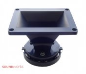
100db soft dome, a new Beyma? 
http://www.beyma.de/fileadmin/seiten/download/pdf/Beyma_professional/2007-M_rz-SMC2012N_1_.pdf
http://www.beyma.de/fileadmin/seiten/download/pdf/Beyma_professional/2007-M_rz-SMC2012N_1_.pdf
Attachments

45EUR btw
Might be easily DIY improved with a roundover mouth 🙂
If its possible to take off the horn it might be easy to improve it
Though it looks like the front poleplate is integrated part of horn
Might be easily DIY improved with a roundover mouth 🙂
If its possible to take off the horn it might be easy to improve it
Though it looks like the front poleplate is integrated part of horn
Torus for full range
Please bear with me if this post is out of place here.
I've seen the good results of 4" dia. tubes at the sides of my present OB. I remember Earl made a comment awhile ago about using a Torus (imagine the shape of an inner tube) as an OB waveguide.
I wonder if using a torus for a 12" full range speaker would be a worthwhile project.
Cutting 6" dia. tubing into an 8 section makeshift torus is one possibility, another is the (temporary) use of a properly sized tire to directly attach the speaker to.
Aside from the crazy looking setup, is there any advice as to the diameter of the torus, the material used, or the cross section ?
If the results are satisfying, I'd plan on making a fiberglas Torus OB.
OB is certainly off topic, but I'll comment briefly. If one wants the lowest possible diffraction from an OB, then the torus does this. However, the dogma for OB is that baffle diffraction is not an issue. I, of course, don't accept this, because there IS a lot of diffraction and I know of no situation where diffraction is a "good thing".
Now, how big should the torus be? Well simply put, the bigger the better, all the way up to an infinite baffle, which has the lowest diffraction of anything. The larger the torus the greater will be the dipole moment and the greater the LF output. It's that simple really. Not much to it.
For material, it should be dead. Foam filled fiberglas would be great. I also though that a truck tire filed with foam and then the tire cut away would be good.
Hope this helps, and I'd love to see some actual data.
gedlee said:
However, the dogma for OB is that baffle diffraction is not an issue.
There are good sim software to deal with this issue 😉
Anyway, I just thought about a short linearray with the cheap dome drive Beyma horn, with say 10 horns each side
Crossed to maybe 6x Beta-8a
Cost would be a problem though, so its not likely to happen

Well, maybe MTM would do
What would happen if 4 of these horns were mounted in a square
Attachments

tinitus said:
What would happen if 4 of these horns were mounted in a square
Nothing good I would imagine.
gedlee said:OB is certainly off topic, but I'll comment briefly. If one wants the lowest possible diffraction from an OB, then the torus does this. However, the dogma for OB is that baffle diffraction is not an issue. I, of course, don't accept this, because there IS a lot of diffraction and I know of no situation where diffraction is a "good thing".
Now, how big should the torus be? Well simply put, the bigger the better, all the way up to an infinite baffle, which has the lowest diffraction of anything. The larger the torus the greater will be the dipole moment and the greater the LF output. It's that simple really. Not much to it.
For material, it should be dead. Foam filled fiberglas would be great. I also though that a truck tire filed with foam and then the tire cut away would be good.
Hope this helps, and I'd love to see some actual data.
Or use a swim ring. And fill it with plaster or concrete.
http://images.google.no/images?hl=no&um=1&sa=1&q=swim+ring&aq=f&oq=
I thought it would be interesting to post comparision of some simulations and the measurement.
Longest curve is the measured.
Smoothest curve is simulation of waveguide in an infinit baffle.
Curve closer to the measurement dip is wave guide lip edge going straight back to an infinit baffle 1M behind.
These sims seem to indicate how the lip rolls back will effect the response.
Any views and comments are wellcome.
An externally hosted image should be here but it was not working when we last tested it.
Longest curve is the measured.
Smoothest curve is simulation of waveguide in an infinit baffle.
Curve closer to the measurement dip is wave guide lip edge going straight back to an infinit baffle 1M behind.
These sims seem to indicate how the lip rolls back will effect the response.
Any views and comments are wellcome.
soongsc said:I thought it would be interesting to post comparision of some simulations and the measurement.
Longest curve is the measured.
Smoothest curve is simulation of waveguide in an infinit baffle.
Curve closer to the measurement dip is wave guide lip edge going straight back to an infinit baffle 1M behind.
These sims seem to indicate how the lip rolls back will effect the response.
Any views and comments are wellcome.
Thanks for sharing!
Despite a small frequency shift that may come from slightly different dimensions in simu horn versus built horn there is remarkable tight correlation at the HF irregularity 20kHz and up.
The ripples (below 20kHz) that do not show up in infinite baffle simu are exactly what showed up as "folds in the skin" of my whale simus.
I did it with the IB of the simu set roughly at the diaphragm plain to get sort of dipole symmetry (which sadly can't mimic "real" dipole behaviour of course).
So I guess I also have to built further prototypes to measure the "real" roughness of FR - just as you did.
Michael
BTW
this is my most recent attempt to bend LeCleach towards constant directivity by using the Gaussian algorithm.


Resolution of simu is moderate 100 points over frequency range shown.
Comparing to the LeCleach simu shown in
http://www.diyaudio.com/forums/showthread.php?postid=1891535#post1891535

we see considerable progress towards CD *without* compromising LeCleach' inherent sound field smootness!
🙂
If we take the yellow color as reference it is visibly more horizontal – with the result that the yellow contour now meets 90deg at roughly 2kHz - half of the 5kHz before.
On-axis and within the +/- 30deg range the overall SPL smoothness has greatly improved as well.
Very encouraging so far.
Michael
this is my most recent attempt to bend LeCleach towards constant directivity by using the Gaussian algorithm.
Resolution of simu is moderate 100 points over frequency range shown.
Comparing to the LeCleach simu shown in
http://www.diyaudio.com/forums/showthread.php?postid=1891535#post1891535
we see considerable progress towards CD *without* compromising LeCleach' inherent sound field smootness!
🙂
If we take the yellow color as reference it is visibly more horizontal – with the result that the yellow contour now meets 90deg at roughly 2kHz - half of the 5kHz before.
On-axis and within the +/- 30deg range the overall SPL smoothness has greatly improved as well.
Very encouraging so far.
Michael
soongsc said:I thought it would be interesting to post comparision of some simulations and the measurement.
Any views and comments are wellcome.
To be truely usefull you need to compare sims with measurements over the total polar response, not just a single axis.
soongsc said:Michael,
What driver model parameters are you using?
Are you using a dome or flat diaphragm?
You know, all my horn work is intended for the AMT driven DiHo I use.
I guess the wave front of an AMT is as close to plain as possible - so I always simulate with flat diaphragms (at least all simus I've pubished so far).
Michael
AMT meaning Air Motion Transformer?mige0 said:
You know, all my horn work is intended for the AMT driven DiHo I use.
I guess the wave front of an AMT is as close to plain as possible - so I always simulate with flat diaphragms (at least all simus I've pubished so far).
Michael
What's DiHo?
I quite agree, but with the limitation of geometry modeling, I doubt they will match close enough. But it's interesting to use sims to figure out what adjustments to make. Hmm, if off axis response curves can be updated in one display, that would be usefull.gedlee said:
To be truely usefull you need to compare sims with measurements over the total polar response, not just a single axis.
- Home
- Loudspeakers
- Multi-Way
- Geddes on Waveguides