gedlee said:
Seems to me that people who are always tweaking are also never satisfied. I would find that frustrating.
Many good things can come out of frustrations, like your Summa and now kits
It seems frustrations can be used positively
But I do know what you mean, and offcourse you are right, satisfaction is good, but also very boring, and I suppose one reason why many of us are here at all 🙂
Hi Earl, soonqsc
The plot I had attached can be thought of by imagining the polar plot for the highest frequency of interest is at the top.
At the bottom is the lowest frequency of interest and in this case there are 200 plots in between the two extremes with MathCAD mapping a surface to the stack..
In this imaginary example, the polar plot of two equal point sources, shows coherent addition at the lowest F (a round pattern) where the acoustic spacing is small and the familiar spider pattern at the top where the increased F produces a spacing of several wavelengths.
The point is, that features that are frequency dependent seem to show up visually depending on the view of the stack. I was thinking that the display while offering no “numbers” might be a visual aid in selling your horns, especially by having some examples of “bad” ones..
I can see how these HOM’s would be hard to see in the amplitude but wonder about time. I am much less familiar with the more popular measuring platforms than with TDS /. TEF but I imagine they could do this too.
To take a TDS / TEF measurement, one first takes an Energy vs time measurement to establish how far away the speaker is in time..
With a linear swept sine, the mic signal appears at a frequency “behind” the sweep by an amount equal to the sweep rate and time delay / distance involved.
These two signals are multiplied together, the sum is rejected while the difference F is read via FFT and re-scaled to read in time.
This result is the ETC / energy vs time, one can also take the real portion of this separately which is the impulse response while the ETC envelope contains both real and imaginary.
Anyway, the linear sweep weighs strongly to higher frequencies (a white spectrum normally desirable in locating the speaker) but if one passes the output signal through a pinking filter, one gets an ETC which is equally weighted.
Then if one did an ETC that only covered say half octave bands starting at 20K and going down, one could have extremely high time resolution and a primary and secondary signals could be resolved easily.
This could be done like a polar plot (many angular measurements) except the feature of interest is time not magnitude
I think the thing in favor of quantifying them would be in that there is only one direct path on axis and all HOM’s would have to fall in behind the direct path time wise.
Soonqcs;
I have to agree completely with Earl, my own experience has also been that speaker companies, especially the larger ones are generally not very interested in outside developments.
When the first Space Shuttle blew up along with our companies “mission”, the company I worked for was faced with a decision of having to try to license some of the speaker things I was doing in the speaker division or else. Now, the thorn in the company’s side, became their possible savior, which was humorous to those who worked in the speaker part.
In that process, among the interesting things that happened was a meeting with the President of EV who after hearing / feeling the Servodrive woofers said “we don’t believe anything below 75 Hz is necessary”. To make a long story short, only a few things were ever licensed and then it was to smaller companies.
I have a couple things under license now but I don’t even bother trying to pitch licensing to anyone, it has only worked when they came to me about it.
If I were Earl, I would do what he is doing now, try to figure out how to reach the people who care about the sound enough to try something other than mass market and copycat stuff..
Best,
Tom Danley
"Seems to me that people who are always tweaking are also never satisfied. I would find that frustrating."
Hello Earl
Well if you are into DIY tweeking and trying to push for improvements is all part of it. You do need to know when to stop though. That's not always easy. I have always had second system that I really like as a baseline and fall back set-up. If I get frustrated or just feel lost I can always power it up and use it as a reference or just take a break for a while.
Rob🙂
Tweaking is good for getting a general feeling in what one can expect. Not accurate, but most of the time rewarding if the tweak is based on experience based intuition. To fine tune, certainly there are lots more involved.
Hopefully satisfaction are short lived, thus the motivation to accomplish more.
Hopefully satisfaction are short lived, thus the motivation to accomplish more.
Hi Tom,
That picture had been in my mind for quite some time. If we look at a baffled piston simulation, quite noticeably you can see a beam, and also the baffle edge acting like a point source of lower intensity. These point sources in a way creates some minor cimplesity in the wave front possibly due to it's phase difference and the way it expands into the main beam. This is the mental image of HOMs I have in my mind for now. This picture also relates with wide band cone drivers as well because at higher frequencies the cone walls are also sources with the cap being the main source (if it has one). The interaction of the multiple modes of the cone and the cap creates something similar to HOMs, but since they are of quite equal magnitude, we just look at them as a whole. But when you start measuring off-axis, the interaction becomes more evident.
My interest in wave guides is to hopefully achieve something that has a wave front as close to a point souce as possible, hopefully can go down to 100Hz and up above 20KHz with home listening levels SPL. Not having a whole lot measured data on these designs, it's going to be tough, but I'm in no hurry.
I do agree licensing to large companies is very difficult, and probably will only come by chance, but I just mentioned B&O so as to still show that there is a possibility. With the current consumer product emphasis on industrial design these days, it's going to be even more difficult if the target market is the mass consumer market. This market is a look special first to attract, sound better to close the deal. Like food, if it looks good, people will at least try it; if it look unfamiliar, fewer people will take interest. I once did something quite similar to the Beolab 5; golly it looked unique. But after I took some measurements, it went to the bottom of my list because I knew it would cast too much investment to even get the measurements to look good. Man there was just so much difraction going on.
Robh3606 said:"Seems to me that people who are always tweaking are also never satisfied. I would find that frustrating."
Hello Earl
Well if you are into DIY tweeking and trying to push for improvements is all part of it. You do need to know when to stop though. That's not always easy. I have always had second system that I really like as a baseline and fall back set-up. If I get frustrated or just feel lost I can always power it up and use it as a reference or just take a break for a while.
Rob🙂
Exactly.
Tom Danley said:Hi Earl, soonqsc
The plot I had attached can be thought of by imagining the polar plot for the highest frequency of interest is at the top.
At the bottom is the lowest frequency of interest and in this case there are 200 plots in between the two extremes with MathCAD mapping a surface to the stack..
If I were Earl, I would do what he is doing now, try to figure out how to reach the people who care about the sound enough to try something other than mass market and copycat stuff..
Best,
Tom Danley
Tom, I understand your plot now, but I don't think that it shows anything that my polar map won't and I find the polar map a lot easier to read.
We are in complete agreement on licensing and the big audio companies. I do believe that they will go down as a result however.
Tom, I found the plot you are talking about. If there were an animation moving from two sources to multiple souces, that would be a nice demonstration.
If I only aimed fore satisfaction I would just keep what I have, but I agree that those just wanting a good speaker should build the kit, fore the same reasons that Earl stated
These may be "better" but they are still too small to have good polar response control (i.e. the response will not be constant directivity, independent of angle). A 10" waveguide is as small as I would ever use, a 12" is much better and it really takes about 15" of diameter to get the polar response to be well controlled down to about 1 kHz. There is also the unbaffled problem. A baffle or enclosure helps out the pattern control because there is less diffraction from the mouth.
hi Earl
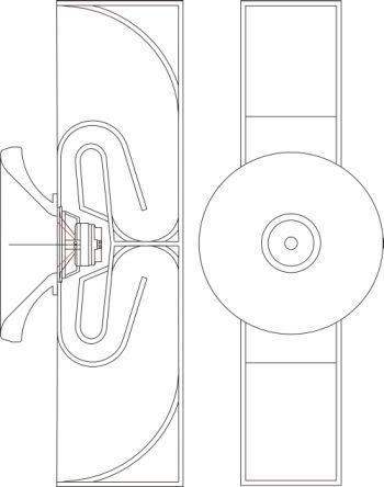
i think a true point source with its coherence is still such a big advantage over two or more separate sources, that it might be worth to continue to think about it, and find a solution to overcome a too small wave guide above 1khz on a 12" driver, like the Great Plains 212-8A . how about to use a additional Wave guide , one like in the drawing, ? I designed one with 30" diameter.
EAW uses a similar, patented solution
Tom Danleys SH50 as well.
Angelo
hi Earl
i think a true point source with its coherence is still such a big advantage over two or more separate sources, that it might be worth to continue to think about it, and find a solution to overcome a too small wave guide above 1khz on a 12" driver, like the Great Plains 212-8A . how about to use a additional Wave guide , one like in the drawing, ? I designed one with 30" diameter.
EAW uses a similar, patented solution
Tom Danleys SH50 as well.
Angelo
angeloitacare said:
i think a true point source with its coherence is still such a big advantage over two or more separate sources, that it might be worth to continue to think about it, and find a solution to overcome a too small wave guide above 1khz on a 12" driver, like the Great Plains 212-8A . how about to use a additional Wave guide , one like in the drawing, ? I designed one with 30" diameter.
Go for it - too risky for my blood since I'm not convinced that it solves a real problem.
hello Earl
you said :
I'm not convinced that it solves a real problem
and
it really takes about 15" of diameter to get the polar response to be well controlled down to about 1 kHz.
if we have 30" , there would be a controll of the polar response well below 1khz, probably 600 - 700hz, which the 1.4" compression driver of the 212-8A would handle pretty well.
And still a point source.
Would that not solve a real problem ?
Angelo
hello Earl
what problems would my solution solve ?
- less diffraction at the horn mouth , since larger size
- directivity matching and fully controlled /uniform dispertion of the full frequency range
- crossover point can be lower, since the bigger WG is able to load the compression driver lower
- woofer size can be smaller - better performance of the 200hz - 1000hz range
- only one mouth, and as consequence
- the best possible imaging as a true point source
BTW, i would use a backloaded horn , and not a regular box, to cover the lowest registers, and make a double horn, like cain & cain Ben, to get a even load of the bass frequencies in the room.
Angelo
Dr. Geddes
if you don't mind, could you specify where our design criterias differ, and where they match, if they do somewhere ?
Angelo
here a drawing of the hole system idea :
if you don't mind, could you specify where our design criterias differ, and where they match, if they do somewhere ?
Angelo
here a drawing of the hole system idea :
The wave guide at 90 degrees, How high directivity control do you have with that? Also, woudn't the disconinuity in the guide cause complicated diffraction problems?
angeloitacare, if you read the thread, it should become obvious why a coaxial in a wg isnt a solution for dr. geddes design criteria. think about the OS shape and what causes HOMs.
The wave guide at 90 degrees, How high directivity control do you have with that?
i will have 90 degree directivity control. Is that not the desired angle, and the standard one used in the OS Wave guide?
Also, woudn't the disconinuity in the guide cause complicated diffraction problems?
This would be one of the compromises. At what point this discontinuity will cause HOM's, Tom Danley probably can respond, since his Unitiy horn also has holes in the wall.
Another compromise would be the size.
As smaller a room, closer to the source is the listening distance. The closer, the more integration of the different channels becomes a issue. Coherence and to obtain good imaging is one of the most important design criterias as well, and the ability of a speaker to " disappear ". Specially for speakers designed for small rooms, this should be taken into consideration.
Angelo
- Home
- Loudspeakers
- Multi-Way
- Geddes on Waveguides