Patrick Bateman said:
According to this site here, it's called "xps foam."
No thats not polyurethane foam board. Its pretty soft, dents easily?
Re: Re: Visualization??
Jean-Michel
Another nice set of pictures, but they are unfortunately not the same as the HOM waves in a waveguide. Those are vibrational modes of a solid and the HOM in a waveguide are propagational modes in a continuous media. While they are mathematically related y the wave equation if the solid is a fluid (unlike the earth), but they are different solutions because the boundary conditions are different.
Jmmlc said:Hello John,
I prefer to see something like that: http://www.pnas.org/content/105/39/14784/F4.medium.gif
and for a second (?) order mode something like that http://www.pnas.org/content/vol0/issue2008/images/data/0803748105/DCSupplemental/SM1.gif
or something like the complex vibrational modes of the Earth:
http://icb.u-bourgogne.fr/Nano/MANAPI/saviot/index.en.html
but at an infinitesimal scale
Best regards from Paris, France
Jean-Michel Le Cléac'h
Jean-Michel
Another nice set of pictures, but they are unfortunately not the same as the HOM waves in a waveguide. Those are vibrational modes of a solid and the HOM in a waveguide are propagational modes in a continuous media. While they are mathematically related y the wave equation if the solid is a fluid (unlike the earth), but they are different solutions because the boundary conditions are different.
Re: Re: Visualization??
As clearly outlined - my "bunch of pretty pictures" never was intended as "data" in its very sense.
They provide understanding of the basic underlying mechanisms involved – lets face it.
Presumably we are not at the same track here – for sure its nothing about "my feelings" – you simply avoided to answer.
Ok then - back to Start of "Question and Answering" again:
🙂
1.) do or don't you agree that HOM is completely defined within the mechanisms of diffraction – reflection – delay – interference (my example of fig1 "wave front propagation in finite pipe with reflection at the mouth" taken from the "bunch of pretty pictures")?
fig 1

2.) in case you (now) don't agree – give a "low level" (for the "dumb one" please!) explanation *why* not.
3.) do or don't you agree that HOM is defined as a specific pattern of the sound field *not* the wave front? (my example of fig3 "stimulation of a infinite pipe with a fixed frequency captured at different phase angles" & fig4 "sound field (pattern) of a infinite pipe stimulated with the same fixed frequency as above" taken from the "bunch of pretty pictures")
fig 3

fig 4

4.) in case you (now) don't agree to 1) and 3) – give a "low level" (for the "dumb one" please!) explanation how the wave *front* can be affected by HOM – ig send a HOM free wave front into a HOM producing horn (my extreme example of fig 2 "wave front propagation in infinite pipe" taken from the "bunch of pretty pictures")
fig 2

5.) did you measure time of arrival or vector to distinguishe wave front from interference?
Michael
gedlee said:
Michael - I appologize if I hurt your feelings with my "pretty pictures" comment. My point was simply that you were jumpng to some very big conclusions based on some weak simulations. In fact I think it was precisely these "pictures" that led you and others to the false conclusions that you still seem to have.
There is no such thing as "created by HOM". Higher order modes are a result not a process.
The comment about the "non-plane wave fronts of a compression driver" is not correct. A plane wave has constant phase AND constant amplitude. A wavefront of constant phase IS NOT a plane wave if the amplitude is not uniform. Thus a phase plug can create a flat wave of constant phase but non-constant amplitude. When coupled to a waveguide, the non-constant amplitude wave from the driver will generate HOM in the waveguide.
As clearly outlined - my "bunch of pretty pictures" never was intended as "data" in its very sense.
They provide understanding of the basic underlying mechanisms involved – lets face it.
Presumably we are not at the same track here – for sure its nothing about "my feelings" – you simply avoided to answer.
Ok then - back to Start of "Question and Answering" again:
🙂
1.) do or don't you agree that HOM is completely defined within the mechanisms of diffraction – reflection – delay – interference (my example of fig1 "wave front propagation in finite pipe with reflection at the mouth" taken from the "bunch of pretty pictures")?
fig 1
2.) in case you (now) don't agree – give a "low level" (for the "dumb one" please!) explanation *why* not.
3.) do or don't you agree that HOM is defined as a specific pattern of the sound field *not* the wave front? (my example of fig3 "stimulation of a infinite pipe with a fixed frequency captured at different phase angles" & fig4 "sound field (pattern) of a infinite pipe stimulated with the same fixed frequency as above" taken from the "bunch of pretty pictures")
fig 3
fig 4
4.) in case you (now) don't agree to 1) and 3) – give a "low level" (for the "dumb one" please!) explanation how the wave *front* can be affected by HOM – ig send a HOM free wave front into a HOM producing horn (my extreme example of fig 2 "wave front propagation in infinite pipe" taken from the "bunch of pretty pictures")
fig 2
5.) did you measure time of arrival or vector to distinguishe wave front from interference?
Michael
Re: Re: Re: Visualization??
Diffraction is on acoustic phenomina and it will generate HOM waves
Reflection is another acoustic phenomina and HOM waves will exhibite it under the right conditions
Delay is another acoustic phenomina and HOM waves will exhibit it
Interference is another acoustic phenomina and HOM waves will exhibit it
Yes, HOM waves are acoustic waves and obey all of the laws of linear acoustics. What exactly does that mean?
No I certainly do not agree with this. An HOM is a wave quite distinct from any other HOM or the main wavefront. The linear superposition of all these waves will yield some "specific pattern of the sound field", but these paterns are the result of the HOM and main wave and NOT the HOM themselves.
I don't understand the question. When I measured what?
Why not add "wave propagation" and make the list complete then of course HOM would be a subset of "everything", but I just don't see the point.mige0 said:
1.) do or don't you agree that HOM is completely defined within the mechanisms of diffraction – reflection – delay – interference )?
Diffraction is on acoustic phenomina and it will generate HOM waves
Reflection is another acoustic phenomina and HOM waves will exhibite it under the right conditions
Delay is another acoustic phenomina and HOM waves will exhibit it
Interference is another acoustic phenomina and HOM waves will exhibit it
Yes, HOM waves are acoustic waves and obey all of the laws of linear acoustics. What exactly does that mean?
mige0 said:
3.) do or don't you agree that HOM is defined as a specific pattern of the sound field *not* the wave front?
No I certainly do not agree with this. An HOM is a wave quite distinct from any other HOM or the main wavefront. The linear superposition of all these waves will yield some "specific pattern of the sound field", but these paterns are the result of the HOM and main wave and NOT the HOM themselves.
mige0 said:
5.) did you measure time of arrival or vector to distinguishe wave front from interference?
Michael
I don't understand the question. When I measured what?
gedlee said:
No thats not polyurethane foam board. Its pretty soft, dents easily?
They sell white foam and pink foam. The pink stuff is quite tough. I tried cutting it with a serrated knife, and it wasn't easy.
That's why I use a table saw to cut it, it's THAT tough.
I'd say it's about twice as dense as "great stuff" foam.
I place 70 lbs of weight on it while it was drying, to insure the gaps were minimal, and the foam didn't compress at all. I'll bet it could take two or three hundred pounds without compression.
Have you seen this site? This boat builder has some neat tricks for fiberglass work, like using sand instead of a vacuum table to create lightweight and strong parts.
http://www.adventuresofgreg.com/HPB/HPBmain.html
Hello,
I was hoping that this separation had been done, but apparently not unfortunately.
Then we cannot know what is the minimum amount of HOM a horn will generate, because we cannot separate it from the total when analysing the measurements. So, designing a minimum HOM horn has to be done in pure mathematical sense only. There seems no way to prove the theory by measurements, as usually in science.
Optimizing only the total HOM may produce good result, but is not the ultimate.
Separation of different HOM's would be needed also to define what is the required quality of the driver, because at some point HOM reduction in driver does not improve the sound because other HOM is becoming the dominant one. Over specifying the driver is expensive at least.
- Elias
Originally posted by gedlee
It would be an almost insurmountable task to derive how much of the HOM at the mouth was due to the three possible sources of HOM creation 1) the driver diaphragm modes 2) the phase plug and interface, 3) the waveguide itself.
I was hoping that this separation had been done, but apparently not unfortunately.
Then we cannot know what is the minimum amount of HOM a horn will generate, because we cannot separate it from the total when analysing the measurements. So, designing a minimum HOM horn has to be done in pure mathematical sense only. There seems no way to prove the theory by measurements, as usually in science.
Optimizing only the total HOM may produce good result, but is not the ultimate.
Separation of different HOM's would be needed also to define what is the required quality of the driver, because at some point HOM reduction in driver does not improve the sound because other HOM is becoming the dominant one. Over specifying the driver is expensive at least.
- Elias
Elias said:
Separation of different HOM's would be needed also to define what is the required quality of the driver, because at some point HOM reduction in driver does not improve the sound because other HOM is becoming the dominant one. Over specifying the driver is expensive at least.
As is overspecing the waveguide, obviously.
Also indeterminate is the level of audibility of HOM anomalies from the several potential sources....

Hello,
Ok.
This is how I understand HOM at the moment:
Let's make an imaginationary test. Put a horn directly in front of the listener. Assume the basic mode is perfect spherical wave so the phase isobars of velocity potential are continous, or maybe better is to say the spatial pressure gradient is monotonic. When the basic mode hits the two ears of the listener the ear signals will be identical.
Then consider an arbitrary higher order mode propagating towards the listener. Let's visualise that HOM like this for example, due to lack of better picture at hand this have to do:
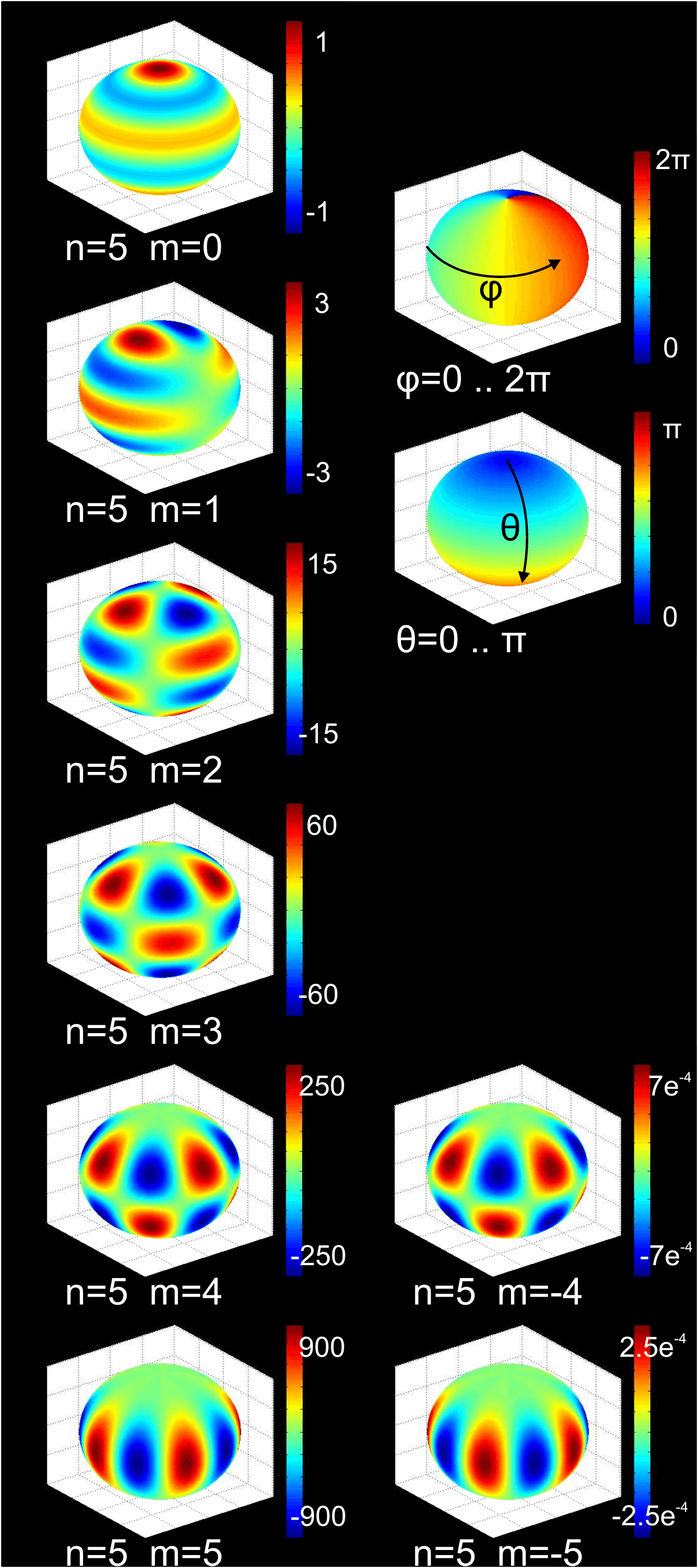
Never mind the numbers and discard the levels. Let's say the 'green ball' is the "hypothetical spherical surface" and blue and red are pressure differences along the sphere. You see there is phase differences along the sphere. What happends when the higher order mode hits the listener ears, the ear signals will not be identical anymore but they are having an amplitude and phase difference depending the location of the listener ears compared the horn axis.
Finally the ear signals will be the sum of the basic mode and all the higher order modes, so the final wavefront will be very complex! Also any spatial movements in relative to the horn axis will produce varying ear signals.
Now we are back into psychoacoustics to define how that would sound like.
Is the delay simply because longer path length, or more complicatedly because a mode of given order takes some time to be developed, and the higher the mode the longer it will take?
- Elias
Edit: Oh no, the picture is huge, cannot edit that..
Originally posted by gedlee
If I measure the wavefront at the mouth of a horn, then I know exactly how it will radiate. Now this wavefront will be the sum over all the modes in a plane aperature, Bessel functions if it is a plane. But these modes are NOT the modes of the waveguide as those are Spherical Harmonics. There is a relationshp between the Spherical Harmonics and the Bessel functions and one could then calculate the wavefront in terms of the Spherical Harmonics. The lowest order mode is that of a uniform velocity profile on a spherical surface. This is the "main mode" of wave propagation in a conical waveguide - all waveguides become conical at the mouth. Now if, and this will almost always be true, there is deviation from a perfectly uniform wavefront on the hypothetical spherical surface in the mouth, then this deviation has to be the result of HOM.
Ok.
This is how I understand HOM at the moment:
Let's make an imaginationary test. Put a horn directly in front of the listener. Assume the basic mode is perfect spherical wave so the phase isobars of velocity potential are continous, or maybe better is to say the spatial pressure gradient is monotonic. When the basic mode hits the two ears of the listener the ear signals will be identical.
Then consider an arbitrary higher order mode propagating towards the listener. Let's visualise that HOM like this for example, due to lack of better picture at hand this have to do:
Never mind the numbers and discard the levels. Let's say the 'green ball' is the "hypothetical spherical surface" and blue and red are pressure differences along the sphere. You see there is phase differences along the sphere. What happends when the higher order mode hits the listener ears, the ear signals will not be identical anymore but they are having an amplitude and phase difference depending the location of the listener ears compared the horn axis.
Finally the ear signals will be the sum of the basic mode and all the higher order modes, so the final wavefront will be very complex! Also any spatial movements in relative to the horn axis will produce varying ear signals.
Now we are back into psychoacoustics to define how that would sound like.
Originally posted by gedlee
In all cases, regardless of the cause, the HOM are dispersive and arrive later than the main mode.
Is the delay simply because longer path length, or more complicatedly because a mode of given order takes some time to be developed, and the higher the mode the longer it will take?
- Elias
Edit: Oh no, the picture is huge, cannot edit that..
Elias said:Then we cannot know what is the minimum amount of HOM a horn will generate, because we cannot separate it from the total when analysing the measurements. So, designing a minimum HOM horn has to be done in pure mathematical sense only. There seems no way to prove the theory by measurements, as usually in science.
Optimizing only the total HOM may produce good result, but is not the ultimate.
Separation of different HOM's would be needed also to define what is the required quality of the driver, because at some point HOM reduction in driver does not improve the sound because other HOM is becoming the dominant one. Over specifying the driver is expensive at least.
I think Earl's words, "almost insurmountable" have to be put in the proper context. It's a matter of the time and money required, as held against the value of the information generated. Or it's a matter of practicality rather than possibility.
The discussions about wave guides and horns of various types have generated lots of information about their potential characteristics. Not as much as we'd all prefer, but, the design choices and trade offs are well enough described even now, to make rational choices, according to one's goals. An early mentor of mine was fond of the saying; "when facts are sufficient, argument is useless". Still plenty of room for argument, but hey, this is DIY and the facts are sufficient to set priorities and be fairly certain of coming up with something that sound good.
Sheldon
Elias said:
Optimizing only the total HOM may produce good result, but is not the ultimate.
- Elias
I have always said this, that the optimum only comes when the drivers are optimized for waveguides. But at any rate, while we may not yet have the optimum, what we do have is a heck of a lot better than what we had say ten years ago.
Elias said:Hello,
Let's make an imaginationary test.
Is the delay simply because longer path length, or more complicatedly because a mode of given order takes some time to be developed, and the higher the mode the longer it will take?
Elias
I don't follow your imaginary test, and your "pretty pictures" don't have anything to do with HOM in a waveguide. Those are spherical radiation modes, not the same thing.
The delay is mostly path length and it is the delay that is most important. Thats because if there was no delay then the HOM would be only affect the main spherical mode radiation pattern by a small amount, nothing to be concerned with. But with the delay we have an entirely different situation audibly and the reason why it's a good idea NOT to lump the HOM into the main wave as "interference patterns" as suggested.
Elias said:
Is the delay simply because longer path length, or more complicatedly because a mode of given order takes some time to be developed, and the higher the mode the longer it will take?
- Elias
Edit: Oh no, the picture is huge, cannot edit that..
What you show is what JMLC did refer to - its not HOM as I understand it - its break up.
Meaning you can force that kind of wave fronts by unequally moving diphragms or due to different times of flight in phase plugs (as long as they are not supressed by the following dimensions) - but not by "natural" HOM (being a property of frequency versus boundary dimensions).
HOM is caused by subsequent actions of diffraction-reflection-delay-interference.
Hence you never get such wave *fronts* from HOM caused by horns - the interferring parts are always too late to the party.
Michael
My gut feeling is that you will get a hump in the middle of the waveguide bandwidth a bit like my previous elliptical test unit posted previously.Patrick Bateman said:
I posted plans for an elliptical waveguide over on my Unity thread. Instead of oblate spheroidal or conical, it uses a bezier curve between the throat and the mouth. Based on an article I read, that's supposed to provide a gentler transition between the coverage angle at the throat and the mouth. Basically it has fewer abrupt changes in directivity, like what you see at the throat and the mouth in a lot of waveguides. Here's a few pics:
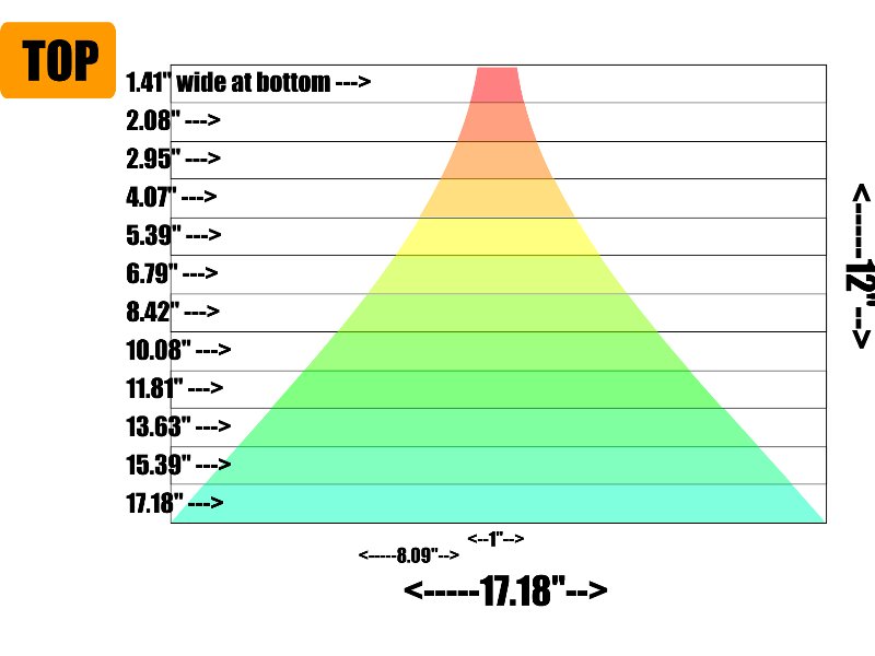
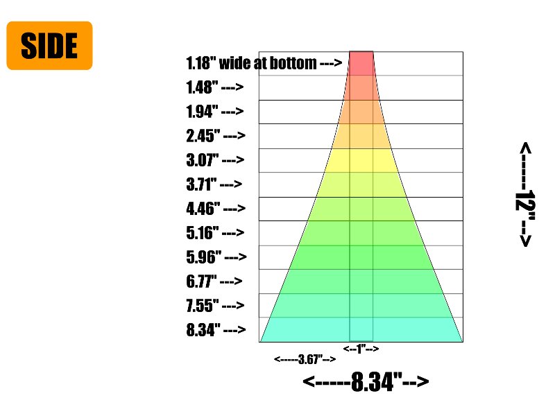
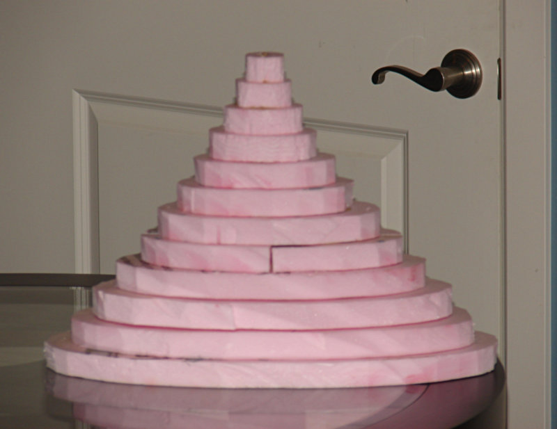
Here's the thread:
http://www.diymobileaudio.com/forum/diy-mobile-audio/60146-creating-perfect-soundstage-1.html
What I would recommend is try and optimise an axi-symmetric one and then ellipticalize it based on maintaining the cross section area expansion.
The way HOM is generated is quite similar is how I understand the situation.tinitus said:
...
Another thing is that the speed defines the curvature needed, more speed less curvature, and low speed more curvature
But completely plane is not good, and results in too much turbulent air and loss of control
Sounds like HOM 😀
mige0 said:HOM is caused by subsequent actions of diffraction-reflection-delay-interference.
Michael
Michael
HOM can be caused by diaphragm breakup. Whenever the wavefront at the throat is not what is allowed by the "main mode" then HOM must be present to make up the difference. For example, an OS waveguide wants a plane wave of constant phase AND amplitude at the throat. When the phase plug is not such that this occurs, such as a non-uniform amplitude across this wavefront, then HOM will be created right at the throat, no diffraction is required at all.
All of you have been been doing some really hard, difficult work...made more difficult because it takes you away from your "comfort" zone...whether that be formulas or illustrations.
There's been a lot accomplished & clarified. Thanks for that. 😉
soonsgc, can you characterise the diffraction from your simulation? Would it be reasonable to conclude that your profile distributes the occurance of diffraction across a wider section of the mouth than the OS?
...and one more thing...let's not start a "dumber than" contest with Mongo in the wings. 😀
gedlee said:
Michael
HOM can be caused by diaphragm breakup. Whenever the wavefront at the throat is not what is allowed by the "main mode" then HOM must be present to make up the difference. For example, an OS waveguide wants a plane wave of constant phase AND amplitude at the throat. When the phase plug is not such that this occurs, such as a non-uniform amplitude across this wavefront, then HOM will be created right at the throat, no diffraction is required at all.
Thats what I said.
simply put - a OS is a duct at its throat and the main mode of a duct is a plane wave front.
Fig2
the transition to conical - where the main mode is different – this is what creates the “natural” HOM
fig5

Sure - HOM can be created by any uneven = *forced* wave front form a driver – but it will straighten out = becoming suppressed
fig4
And for me – its way better (more clear) to say the *diffraction* is what have to make up for the difference (in change of the wave front shape = main mode) than to say the HOM is what has to make up for the difference
Michael
The original idea was to distribute diffraction over a wider spectrum, but in the simulation process, directivity control with parrallel SPL curves took a more important roll in the decision. Somehow, things just fell into place. Nature is wonderfull.Ed LaFontaine said:All of you have been been doing some really hard, difficult work...made more difficult because it takes you away from your "comfort" zone...whether that be formulas or illustrations.
There's been a lot accomplished & clarified. Thanks for that. 😉
soonsgc, can you characterise the diffraction from your simulation? Would it be reasonable to conclude that your profile distributes the occurance of diffraction across a wider section of the mouth than the OS?
...and one more thing...let's not start a "dumber than" contest with Mongo in the wings. 😀
Re: Re: Re: Visualization??
Hello Earl,
In many mechanicals problems (including fluid mechanics) macroscopic behavior can be explained by some behaviour of the medium at a microscopical scale (= on infinitesimal volumes).
Colleagues of mines even use soft /hard/frictional spheres assembly models to study rock mechanics (for non granular materials).
I am a bit disappointed to learn that HOM cannot be described by how the air behave at an infinitesimal scale (statistically) by example as a pulsating sphere (mode of vibration 1) for plane propagation and as a pulsating ellipsoid when the sphere as encoutered a more rigid boundary...
As I teached since 32 years I consider that simple good imaging is very helpful from a pedagogical point of view.
Best regards from Paris, France
Jean-Michel Le Cléac'h
gedlee said:
Jean-Michel
Another nice set of pictures, but they are unfortunately not the same as the HOM waves in a waveguide. Those are vibrational modes of a solid and the HOM in a waveguide are propagational modes in a continuous media. While they are mathematically related y the wave equation if the solid is a fluid (unlike the earth), but they are different solutions because the boundary conditions are different.
Hello mige0,
No, the notion I introduced is different than what Elias is referring to.
In my message I didn't consider the macroscopical scale as Elias did, but I was asking what happen at an infinitesimal scale near a boundary, that means how minute elements (volumes of air) having along time a mean shape being a sphere strain after interaction with the boundary (or with other neighbours elements) and how those minute volumes interacts to develop what we see at the macroscopical scale.
I am surprised that this problem of HOMs cannot be illustrated at the lowest scale and could only be explained at the macroscopical scale.
Best regards from Paris, France
Jean-Michel Le Cléac'h
mige0 said:
What you show is what JMLC did refer to - its not HOM as I understand it - its break up.
Meaning you can force that kind of wave fronts by unequally moving diphragms or due to different times of flight in phase plugs (as long as they are not supressed by the following dimensions) - but not by "natural" HOM (being a property of frequency versus boundary dimensions).
HOM is caused by subsequent actions of diffraction-reflection-delay-interference.
Hence you never get such wave *fronts* from HOM caused by horns - the interferring parts are always too late to the party.
Michael
Jmmlc said:Hello mige0,
No, the notion I introduced is different than what Elias is referring to.
In my message I didn't consider the macroscopical scale as Elias did, but I was asking what happen at an infinitesimal scale near a boundary, that means how minute elements (volumes of air) having along time a mean shape being a sphere strain after interaction with the boundary (or with other neighbours elements) and how those minute volumes interacts to develop what we see at the macroscopical scale.
I am surprised that this problem of HOMs cannot be illustrated at the lowest scale and could only be explained at the macroscopical scale.
Best regards from Paris, France
Jean-Michel Le Cléac'h
Oh - got it.
In addition to FEM / BEM.. it should be “easy 😀” to do with elastic bubbles.
Think of it like filling the horn (and the room) with billiard balls – get your cue instead of a speaker – and calculate the impulse front propagating through all balls.
Would give another bunch of beautiful pictures for sure
🙂
The unsymmetry of the infinitesimal deformation of the balls is what you are looking for I guess?
Michael
- Home
- Loudspeakers
- Multi-Way
- Geddes on Waveguides