mige0 said:It tells us that HOM in fact is a subset of "diffraction- reflection- delay- interference" which you consistently avoided to confirm when I've come up with .
I don't understand what's going on here. Obviously, if HOM consist of diffraction, reflection, and the resulting delay, they are a subset of diffraction-reflection-delay-interference. Earl has described this numerous times in numerous ways. Why does anyone need to confirm that three things out of four define a subset of the four? What I don't know is what the set of four is supposed to signify - all the things that cause non-linear distortion in a horn/WG, some of them?
mige0 said:The logically consequence I did some earlier
( in http://www.diyaudio.com/forums/showthread.php?postid=1848339#post1848339 )
is that HOM in its sonic outcome is – at best – related to specific interaction with the driver (as outlined by Bjorn) or specific masking effects of our hearing ability.
You've lost me here (yeah, I know, easy to do). I can't make sense of this statement. Where do masking effects come in?
mige0 said:It simply can't be specific to HOM but must apply to all other sound fields of a certain degree of defectiveness / raggedness caused by interference.
Some quite substantial conclusions for now
You seem to be saying that what we hear as the horn character, or raggedness is interference and only that. Earl postulates that HOM, as he has defined them are part of the cause. Is this your message?
For the life of me, I can't figure out why this thing goes round and round. Earl studied the issue of wave propagation in horns/WG's, concluded that some HOM are generated acoustically in the horn, mathematically modeled the problem, came up with designs to minimize this issue, and tested them. Based on the expected nature of propagation of these HOM, foam was added to attenuate them further (or it was tested for some other reason, and its affect rationalized, based on this understanding). The net result is a series of design prescriptions for minimizing these HOM. Subjectively, these correlate with a reduction in "horn character" and/or "harshness". The fact that the hypothesis is consistent with subjective findings, is evidence in favor of the hypothesis, but it is not proof.
Now if you can come up with alternative hypothesis, that shows no correlation with these HOM, yet better predicts designs that have no "horn character, nor harshness" (quotation marks added, because we have no definitive definitions of these terms), you can say that these HOM are not relevant. Or maybe that other factors explain the entire problem and we should concentrate our efforts on those. Really strong evidence would be a design that should generate lots of these HOM, as predicted by Earls models, yet sounds just as good as those using his prescriptions.
Until someone does that, I think that the most practical approach is to follow Earl's prescriptions, or at least consider steps to minimize these HOM. Gosh, what's so controversial about that?
This is not all just talk on my part. I do have waveguides (Unity Horns), I did perceive a slight "horn character". I added foam (only from the phase plug about to about midway to the mouth). The horn character was completely eliminated to my ears. My definition of horn character, is an echo like quality - sounds just like talking through a megaphone in character, but less pronounced. I believe that the distinction between this and other sources of distortion are important.
I think that echo's are quite distinct from steady state resonances, both in cause and quality. So if HOM are indeed like an echo, they would sound different, and be generated by different mechanisms than some other resonances, or interferences such as intermodulation effects. These may be tricky to tease apart with our usual measuring method, but our hearing system can distinguish them. After all, it pretty easy to follow the melody of a violin in a large ensemble - and know that it is a violin. Try to pick that out by measurement.
Sheldon
Instead of saying HOM, why don't we just say resonance? That would be less mysterious and that is how people usually think of HOM elsewhere (in room acoustics for example).
Rybaudio said:Instead of saying HOM, why don't we just say resonance? That would be less mysterious and that is how people usually think of HOM elsewhere (in room acoustics for example).
Except that an HOM can exist with no resonance involved. We don't call HOM in ducts resonances for very good reason. Now they CAN resonate, but that is not a requirement. HOM are an alternate allowed form of wave propagation.
And any why should we change the name of HOM it is a perfectly correct description.
Sheldon
Nice discussion. I hope people get the message, I am affraid that they won't and this will just go on and on as it has been.
Sheldon, I think Michael got offended when Earl dismissed his CARA sims as pretty pictures with no meaning. Personally, I found them helpful. Earl is a mathematician and, to him, equations are the best way to communicate concepts and anything else is irrelevant. Not everyone understands that and sometimes they do better with a picture. I guess I'm in that camp although I'm reasonably well versed in mathematics. Earl's recent paper on distortion was, of course, mathematically correct but his differential equations didn't really tell me as much as actually plotting the 2nd through 9th harmonics on a graph, understanding that Earl weights the higher harmonics more heavily.
And, lest someone think I'm stupid because I prefer visuals, consider Stephen Hawking. He was an equation guy until his disability made it difficult for him to use them. He needed to come up with a way to do things in his head and turned to imagining graphic representations of the concepts. That's when he started making some of his major breakthroughs in physics.
And, lest someone think I'm stupid because I prefer visuals, consider Stephen Hawking. He was an equation guy until his disability made it difficult for him to use them. He needed to come up with a way to do things in his head and turned to imagining graphic representations of the concepts. That's when he started making some of his major breakthroughs in physics.
Dennis,
Appreciated. Most of the math is over my head. I like graphics too, and differential equations were long ago for me, and mostly forgotten due to underuse. My hope is that we can get back to meaningful discussions that the less technical among us can still benefit from. I hope everyone can take a breath, try to temper our comments, and reactions, and focus on exploring the issues. There are good kernels among the chaff. I think we can up the ratio.
You will hear no more from me, other than strictly technical issues (mostly questions).
Sheldon
soongsc said:
Don't you think the curves look seducing?😉
Yes thanks
Looks a bit like an OS, with light curvature instead of "plane" transition, if those are the right words
And I have been thinking the same
My experience comes from windsurfing, making both fins and boards Which in theory is kind of the same thing as aerodynamics, which leads to sound waves as well
It has tought me that completely plane is to be avoided because only certain curves are able to maintain control over the media, which is air or water
Another thing is that the speed defines the curvature needed, more speed less curvature, and low speed more curvature
But completely plane is not good, and results in too much turbulent air and loss of control
Sounds like HOM 😀
catapult said:Sheldon, I think Michael got offended when Earl dismissed his CARA sims as pretty pictures with no meaning. Personally, I found them helpful. Earl is a mathematician and, to him, equations are the best way to communicate concepts and anything else is irrelevant. Not everyone understands that and sometimes they do better with a picture.
When I first got into waveguides, I didn't understand how simple they are. I spent a few hours trying to absorb the equations in Earl's book, but lost the plot somewhere around page two.
The next day, I sheepishly asked Dr Geddes where the equation to plot an oblate spheroidal waveguide was in his book. I figured I'd missed it somewhere.
Turns out it's not in either of his books!
He wrote in on a napkin for me, in ballpoint pen, and I used that napkin to create a spreadsheet the next week... 😀
soongsc said:
Don't you think the curves look seducing?😉
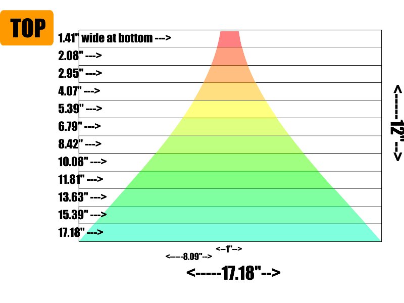
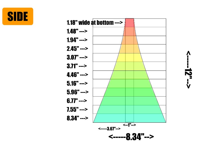
I posted plans for an elliptical waveguide over on my Unity thread. Instead of oblate spheroidal or conical, it uses a bezier curve between the throat and the mouth. Based on an article I read, that's supposed to provide a gentler transition between the coverage angle at the throat and the mouth. Basically it has fewer abrupt changes in directivity, like what you see at the throat and the mouth in a lot of waveguides. Here's a few pics:
Here's the thread:
http://www.diymobileaudio.com/forum/diy-mobile-audio/60146-creating-perfect-soundstage-1.html
Thanks all of you for your patience and willingness to spot the point !
Basically I come from a point of view that doesn't follow the logic of Earls arguments – not to say that I know better – but its my questioning of the weak parts that *may* lead to further insight (and also make the sparks fly).
Two things to me seemed to be the logically steps when I run into the horn thing
1) quantify HOM
2) to get a “more precise” understanding of HOM
ad 2) there was a lot of guess work around whats *exactly* included or not in HOM till Earls confirmation in his latest posting – maybe its been just me – but look at the other tread about measuring HOM (or go back some pages in this thread) and judge by yourself
ad 1) based on my “bunch of pretty pictures” I proposed a set of setups and defined some points where we possible have good chances to measure (the lumped part of) HOM .
Earl pointed out that he thinks HOM would average to zero at the driver and hence this is no good starting point (for the lumped part) whereas I – given the sims are fairly ok quality wise – would expect the bouncing wave fronts could be isolated measuring the driver.
I think both points are valid to follow further on – no?
I guess this picture you give, is what I stumbled across and what I questioned from the very beginning.
Maybe I simply got you wrong as you are a little bit imprecise (no accuse meant- really!)
Looking at my “bunch of pretty pictures” we see that the wave *front* isn't exactly allowed to have HOM shape .
This is something to keep clear as the wave *front* shape is unaffected by whatever interferences (HOM included)
I once – implicitly – asked you how you measured the shape of the wave fronts.
If I may repeat my question:
did you measure time of arrival or vector to distinguishe wave front from interference?
😉
Michael
Sheldon said:
You've lost me here (yeah, I know, easy to do). I can't make sense of this statement. Where do masking effects come in?
...
You seem to be saying that what we hear as the horn character, or raggedness is interference and only that. Earl postulates that HOM, as he has defined them are part of the cause. Is this your message?
...
For the life of me, I can't figure out why this thing goes round and round.
…
The net result is a series of design prescriptions for minimizing these HOM. Subjectively, these correlate with a reduction in "horn character" and/or "harshness".
Sheldon
Basically I come from a point of view that doesn't follow the logic of Earls arguments – not to say that I know better – but its my questioning of the weak parts that *may* lead to further insight (and also make the sparks fly).
Two things to me seemed to be the logically steps when I run into the horn thing
1) quantify HOM
2) to get a “more precise” understanding of HOM
ad 2) there was a lot of guess work around whats *exactly* included or not in HOM till Earls confirmation in his latest posting – maybe its been just me – but look at the other tread about measuring HOM (or go back some pages in this thread) and judge by yourself
ad 1) based on my “bunch of pretty pictures” I proposed a set of setups and defined some points where we possible have good chances to measure (the lumped part of) HOM .
Earl pointed out that he thinks HOM would average to zero at the driver and hence this is no good starting point (for the lumped part) whereas I – given the sims are fairly ok quality wise – would expect the bouncing wave fronts could be isolated measuring the driver.
I think both points are valid to follow further on – no?
gedlee said:
HOM are an alternate allowed form of wave propagation.
I guess this picture you give, is what I stumbled across and what I questioned from the very beginning.
Maybe I simply got you wrong as you are a little bit imprecise (no accuse meant- really!)
Looking at my “bunch of pretty pictures” we see that the wave *front* isn't exactly allowed to have HOM shape .
This is something to keep clear as the wave *front* shape is unaffected by whatever interferences (HOM included)
I once – implicitly – asked you how you measured the shape of the wave fronts.
If I may repeat my question:
did you measure time of arrival or vector to distinguishe wave front from interference?
catapult said:Earl is a mathematician and, to him, equations are the best way to communicate concepts and anything else is irrelevant. Not everyone understands that and sometimes they do better with a picture.
😉
Michael
Hi Patrick,
The mold looks cool.
Say, for maintaining the control on both H and V directions, do they have to be the same length along the inner surface from throat to mouth?
I mean, in a circular WG, it's symmetrical in all directions and identical length from throat to everywhere on mouth. In this elliptical WG (or any other horns with elliptical exits), the distance from throat to V sides is shorter than to H sides. So I imagine the wavefront 'escapes' the mouth earilier on the V and later on the H.
How would this affect the directivity control or sound characters? Or, would it need some kind of longer 'lips' on the V sides?
Hello,
Earl explained HOMs from a mathematical perspective in message:
http://www.diyaudio.com/forums/showthread.php?postid=1850353#post1850353
That's OK for me. The scale of this description is macroscopic (the wavefront). But, is it possible to illustrate HOMs physically at a microscopic scale ( = on an infenitesimal volume of air)?
By example we could say that the first order mode is represented by a pulsating sphere, the second order by a pulsating ellipsoide, another order by a pulsating rotating shape.... ...
This will probably a better illustration than a series of Bessel functions...
Best regards from Paris, France
Jean-Michel Le Cléac'h
Jmmlc said:Hello,
Earl explained HOMs from a mathematical perspective in message:
http://www.diyaudio.com/forums/showthread.php?postid=1850353#post1850353
That's OK for me. The scale of this description is macroscopic (the wavefront). But, is it possible to illustrate HOMs physically at a microscopic scale ( = on an infenitesimal volume of air)?
By example we could say that the first order mode is represented by a pulsating sphere, the second order by a pulsating ellipsoide, another order by a pulsating rotating shape.... ...
This will probably a better illustration than a series of Bessel functions...
Best regards from Paris, France
Jean-Michel Le Cléac'h
*if* we continue with the definition we have recently agreed on about whats HOM and what isn't – the wave *front* isn't affected by HOM.
One other aspect *if* we continue to agree on that definition is – that the non plane wave fronts of a compression driver may *only* be caused by different time of flight due to different paths they are squeezed in.
This – in my understanding – would also exclude them from being called "created by HOM".
Michael
Hi,
my first post here. 😎 To introduce myself: My Name is Denis and I'm a student of electro engineering in Ulm/Germany.
I tried to understand HOM, but yet I didn't find a summary. This Thread is too big for me to read. So I have a few dumb questions and I'm sorry if this disturbs this thread.
First of all: Is there a good summary which explains HOM and how they come into existence?
As long as I understood:
If there is a disconuity/interruption/step in the horn, there's of course a reflection and due to this reflecion a bit of the wave travels back into the compression driver and will be reflected again.
So HOM are nothing but standing waves?
I used a BMS 2193 Horn ( [url]http://www.bmspro.info/2193.bms_2193_horn_sound_wave_guide.0.html[/ul]) with a Beyma compression driver. In the horizontal plane the horn is nearly conical. So there's a severe edge at the horn throat. At about 3kHz there's a 3dB-bump in the amplitude response due to a standing wave (= HOM?!).
If the response is equalized, the horn doesn't sound like a horn/honk. There is no critical band in the radiation or in the group delay or rather in the impulse response. Of course you can see that there is a standing wave but no parameter is critical/audible.
(Furthermore the horn sounds as soft and clear as a dome tweeter because of the wide radiation angle especially in the upper octave.)
Thank you.
Visualization??
Something acoustically analogous to this, perhaps??
http://www.falstad.com/embox/guide.html
John L.
Jmmlc said:Hello,
Earl explained HOMs from a mathematical perspective in message:
http://www.diyaudio.com/forums/showthread.php?postid=1850353#post1850353
That's OK for me. The scale of this description is macroscopic (the wavefront). But, is it possible to illustrate HOMs physically at a microscopic scale ( = on an infenitesimal volume of air)?
By example we could say that the first order mode is represented by a pulsating sphere, the second order by a pulsating ellipsoide, another order by a pulsating rotating shape.... ...
This will probably a better illustration than a series of Bessel functions...
Best regards from Paris, France
Jean-Michel Le Cléac'h
Something acoustically analogous to this, perhaps??
http://www.falstad.com/embox/guide.html
John L.
CLS said:Hi Patrick,
The mold looks cool.
Say, for maintaining the control on both H and V directions, do they have to be the same length along the inner surface from throat to mouth?
I mean, in a circular WG, it's symmetrical in all directions and identical length from throat to everywhere on mouth. In this elliptical WG (or any other horns with elliptical exits), the distance from throat to V sides is shorter than to H sides. So I imagine the wavefront 'escapes' the mouth earilier on the V and later on the H.
How would this affect the directivity control or sound characters? Or, would it need some kind of longer 'lips' on the V sides?
As I understand it, the angle of a waveguide simply controls the coverage pattern. So if you have flat sides and a constant coverage angle, all the little pieces fall into place.
IE, you get smooth polar response that doesn't jump around at different frequencies.
So I haven't spent a lot of time wondering how the wavefront behaves, I just know that it measures well. I *did* spend a few hours trying to wrap my brain around a bispheroidal waveguide, which Geddes recommended a few years back, but didn't want to hassle with a mold that complex. (A bispheroidal WG looks like a figure eight.)
In the thread that I referenced, I did polar measurements of a 108x72 degree OS waveguide, and it was very smooth. Another "waveguide" that I built was not.
I started building this new mold because I need a tighter pattern, 108 degrees is too wide.
Re: Visualization??
Michael - I appologize if I hurt your feelings with my "pretty pictures" comment. My point was simply that you were jumpng to some very big conclusions based on some weak simulations. In fact I think it was precisely these "pictures" that led you and others to the false conclusions that you still seem to have.
There is no such thing as "created by HOM". Higher order modes are a result not a process.
The comment about the "non-plane wave fronts of a compression driver" is not correct. A plane wave has constant phase AND constant amplitude. A wavefront of constant phase IS NOT a plane wave if the amplitude is not uniform. Thus a phase plug can create a flat wave of constant phase but non-constant amplitude. When coupled to a waveguide, the non-constant amplitude wave from the driver will generate HOM in the waveguide.
HOM can be generated as you say at a "disconuity/interruption/step in the horn", which will create bascially two HOM at this point. One propagates down stream and radiates and the other propagates up stream and can be reflected off of the diaphragm to become a resonance, but only if the phase and timing of this process is correct.
Hence while an HOM can become a standing wave, this is the exception rather than the norm and all of the timings and phases have to be correct for this to occur - just like a standing wave for the main mode (only certain frequencies of these waves will become standing waves not all frequencies).
I love Falstad's stuff and I use it extensively in my classes, but I find it hard to see the "modes" in the simulation that you provide, although these are HOM for a rectangular duct. They are quite a bit more complicated for a waveguide.
mige0 said:
One other aspect *if* we continue to agree on that definition is – that the non plane wave fronts of a compression driver may *only* be caused by different time of flight due to different paths they are squeezed in.
This – in my understanding – would also exclude them from being called "created by HOM".
Michael
Michael - I appologize if I hurt your feelings with my "pretty pictures" comment. My point was simply that you were jumpng to some very big conclusions based on some weak simulations. In fact I think it was precisely these "pictures" that led you and others to the false conclusions that you still seem to have.
There is no such thing as "created by HOM". Higher order modes are a result not a process.
The comment about the "non-plane wave fronts of a compression driver" is not correct. A plane wave has constant phase AND constant amplitude. A wavefront of constant phase IS NOT a plane wave if the amplitude is not uniform. Thus a phase plug can create a flat wave of constant phase but non-constant amplitude. When coupled to a waveguide, the non-constant amplitude wave from the driver will generate HOM in the waveguide.
Denis D. said:
First of all: Is there a good summary which explains HOM and how they come into existence?
As long as I understood:
If there is a disconuity/interruption/step in the horn, there's of course a reflection and due to this reflecion a bit of the wave travels back into the compression driver and will be reflected again.
So HOM are nothing but standing waves?
HOM can be generated as you say at a "disconuity/interruption/step in the horn", which will create bascially two HOM at this point. One propagates down stream and radiates and the other propagates up stream and can be reflected off of the diaphragm to become a resonance, but only if the phase and timing of this process is correct.
Hence while an HOM can become a standing wave, this is the exception rather than the norm and all of the timings and phases have to be correct for this to occur - just like a standing wave for the main mode (only certain frequencies of these waves will become standing waves not all frequencies).
auplater said:
I love Falstad's stuff and I use it extensively in my classes, but I find it hard to see the "modes" in the simulation that you provide, although these are HOM for a rectangular duct. They are quite a bit more complicated for a waveguide.
Patrick Bateman said:
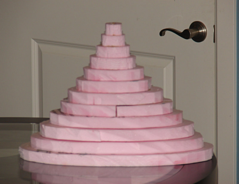
I posted plans for an elliptical waveguide over on my Unity thread. Instead of oblate spheroidal or conical, it uses a bezier curve between the throat and the mouth. Based on an article I read, that's supposed to provide a gentler transition between the coverage angle at the throat and the mouth. Basically it has fewer abrupt changes in directivity, like what you see at the throat and the mouth in a lot of waveguides. Here's a few pics:
[
Hey John
Are you using polyurethane boards now? Thats what they look like.
Re: Visualization??
Hello John,
I prefer to see something like that: http://www.pnas.org/content/105/39/14784/F4.medium.gif
and for a second (?) order mode something like that http://www.pnas.org/content/vol0/issue2008/images/data/0803748105/DCSupplemental/SM1.gif
or something like the complex vibrational modes of the Earth:
http://icb.u-bourgogne.fr/Nano/MANAPI/saviot/index.en.html
but at an infinitesimal scale
Best regards from Paris, France
Jean-Michel Le Cléac'h
auplater said:
gedlee said:
Hey John
Are you using polyurethane boards now? Thats what they look like.
According to this site here, it's called "xps foam."
http://www.8linx.com/cnc/day5.htm
There are some neat pictures of how it can be cut using a PC:
An externally hosted image should be here but it was not working when we last tested it.
I cut it using a table saw, not a hot wire. Goes through like a hot knife through butter.
I've made molds using comic book backing boards, plywood, and foam. Wood is a hassle; takes waaaaaaaay too long to build up the layers.
Re: Re: Visualization??
Earl, I agree re: "seeing the modes"... I like to use the x-y-z slice feature when trying to explain wave propagation in a non-mathematical format when someone shows any interest...
yes, understood this is a simplification for sure...
I also find it useful to use the modal matrix at the bottom to stack the different orders showing their cumulative interactions, within the context of their limitations of course...
John L.
gedlee said:
<snip>
I love Falstad's stuff and I use it extensively in my classes, but I find it hard to see the "modes" in the simulation that you provide, although these are HOM for a rectangular duct.
Earl, I agree re: "seeing the modes"... I like to use the x-y-z slice feature when trying to explain wave propagation in a non-mathematical format when someone shows any interest...
gedlee said:
They are quite a bit more complicated for a waveguide.
yes, understood this is a simplification for sure...
I also find it useful to use the modal matrix at the bottom to stack the different orders showing their cumulative interactions, within the context of their limitations of course...
John L.
- Home
- Loudspeakers
- Multi-Way
- Geddes on Waveguides