I agree with this. But I also think that Engineers should use test methods that can best identify where a problem is if there is any, and qualification test methods be used to judge how it will sound. These will be two groups of tests that may not initially be compatible, but hopefully will be a starting point for each group trying to improve their own test methods until they are somehow related.gedlee said:
It matters not what the mechanism is for low level distortion only that it is the low level distortion that is audible. If you want to design for the numbers thats fine - you will get the kind of amplifiers that enumerate today and the discussions about which amplifier sounds best will continue.
But if you want to design amps that "sound good" then you have to design for audibility, and its the low level stuff that matters, regardless of where or how this occurs.
Until measurements can be proven to correlate with subjective impression - and I and others have clearly shown that they don't - its simply a numbers game with no relavence to reality.
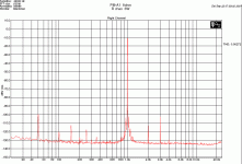
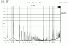
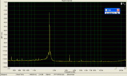
Andrew, try to magnify the image. At 20W,
2nd = -101dB (compared to 1st, 1kHz)
3rd = -79dB
4rd = -109dB
5th = -102dB
No higher harmonics measurable.
Max. is 30W/8ohm.
2nd = -101dB (compared to 1st, 1kHz)
3rd = -79dB
4rd = -109dB
5th = -102dB
No higher harmonics measurable.
Max. is 30W/8ohm.
gedlee said:
Sir - I sometimes think that you post just to stir up flame wars. Please desist as we are having a discussion here that has some merit.
Amplifier distortion measurement results differ disnificantly with varying loads imposed by the speakers. Wouldn't it be more representative for amplifiers to be tested with some impedances that more closely resemble speakers systems instead of a purely dissipative load? Wouldn't it more closley represent how an amp would sound in real world?
Just in my own experience, when I conduct amp distortion measurements with a speaker connected, and change speaker cables, the results do vary. Some amplifiers show less variation to the same loading condition.
No need to get personal.
Hi
Earl, yes you are right of course. It was a simple 1 kHz stimulus just to show a reference for what can be achieved " normally "
PMA, can you provide a measurement of your soundcard alone to show its limits ?
Telling from the pics above it is also 24 bit with its noise floor around –120 dB.
For easy comparing I suggest the pics should be normalised to 0 dB stimulus and made in 20 dB steps like Earl did in his first one.
With SpectraLab you also should have the possibility to freeze several measurements in one print ( at least my version can do that ).
Greetings
Michael
gedlee said:
OOPs Hit "Submit" a bit too soon.
Thanks for that link. His stuff looks very interesting. I may try it out.
But, you could not be doing what I suggested because 1 kHz cannot exactly fit into any time base that I know of so your averaging cannot be sychronous.
Earl, yes you are right of course. It was a simple 1 kHz stimulus just to show a reference for what can be achieved " normally "
PMA, can you provide a measurement of your soundcard alone to show its limits ?
Telling from the pics above it is also 24 bit with its noise floor around –120 dB.
For easy comparing I suggest the pics should be normalised to 0 dB stimulus and made in 20 dB steps like Earl did in his first one.
With SpectraLab you also should have the possibility to freeze several measurements in one print ( at least my version can do that ).
Greetings
Michael
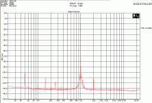
My measurement limit is like below. I use sine generator and -100dB/dec LP filter to remove generator harmonics. Generator without filter has 0.003% THD, but some harmonics up to 9th.
0dB here is 1Vrms. The card has fine distortion from -10dBVrms lower, it increases between -10dB and 0dB to some 0.0025%. For about -15dB, the distortion is about 0.0009%, that is my limit.
Dynamic range is up to some 135dB (for 64K record, this is important), but then the card distortion increases.
For the amplifier measurement, there was a voltage divider of some 26dB attenuation in front of the measuring card. The card input accepts no more than some 1Vrms and has low distortion up to some 300mVrms.
Attachments
Is that a passive filter? 5pole if my sums are right?PMA said:My measurement limit is like below. I use sine generator and -100dB/dec LP filter to remove generator harmonics. Generator without filter has 0.003% THD, but some harmonics up to 9th.
How effective is it in reducing the measurable distortion, i.e. what does 0.003% become after filtering?
Any chance of a schematic?
It is the active filter. Sallen-Key. 2 blocks, 3rd order + 2 order.
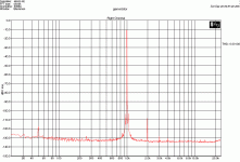
But the 2nd harmonic component is most probably that of the soundcard. So I do not know the distortion of the generator + filter itself. Another image here, generator + filter + soundcard (my limit at -15dBVrms):
But the 2nd harmonic component is most probably that of the soundcard. So I do not know the distortion of the generator + filter itself. Another image here, generator + filter + soundcard (my limit at -15dBVrms):
Attachments
Theoretically this is ideal, but I'm sitting here thinking about a few things:gedlee said:
...
I use a signal that exactly fits into the time base of the A/D taking the data. This means that I don't have to use a window and I can sychronously average a signal to noise ratio that is about 20 dB better than a simpler test could achieve. This means for example that the input signal needs to be something like 976 Hz, not 1000 Hz, which doesn't exactly fit the window.
I actually had to generate the input wav file in FORTRAN using quad precision, special random number generators and rounding techniques, because the test signals needed to have a 120 dB dynamic range - very difficult with 16 bits.
...
1. In Windows, there is no mechanism to synchronize the data sent with the data read. There is not even any way to assure that the output to the D/A is in the precision required because Windows does not have a real time kernal, and if I remember correctly, the PC clock counter resolution is not that good.
2. There is no way to synchronize the transfer with D/A conversion.
3. Then you have the phase shift in the DUT itself.
The best that is possible would be to insert some marker for data alignment which then some post processing before calculating the distortion might be necessary. This post processing is possibly where you really need the precision. Then comes the question of how often do you need to have the embedded marker to that it can distinguish between DUT distortion and clock jitter in the A/D and D/A process plus the associated non-linearity?
soongsc said:
... when I conduct amp distortion measurements with a speaker connected, and change speaker cables, the results do vary.
Unless you are using completely junk or broken speaker cables, this is absurd.
soongsc said:
In Windows, there is no mechanism to synchronize the data sent with the data read. There is not even any way to assure that the output to the D/A is in the precision required because Windows does not have a real time kernal, and if I remember correctly, the PC clock counter resolution is not that good.
This is incorrect basically because it doesn't matter. Sound cards operate independently of windows and don't rely on the PC clock.
But if a very large number of time sychronous samples are used, then it is important that the clocks for the input signal and the sampled data signal be close to one another or the averaging will begin to reduce the signal along with the noise. Note that I said "close" to one another - they don't even have to be exact, the amount of difference will set the SN ratio.
PMA said:It is the active filter. Sallen-Key. 2 blocks, 3rd order + 2 order.
But the 2nd harmonic component is most probably that of the soundcard. So I do not know the distortion of the generator + filter itself. Another image here, generator + filter + soundcard (my limit at -15dBVrms):
I would want to see the amp data at .001 watt, and maybe even lower. As low as you can measure it reliably. 1 watt is a very high SPL level.
gedlee said:
I would want to see the amp data at .001 watt, and maybe even lower. As low as you can measure it reliably. 1 watt is a very high SPL level.
I have not stored such files. This is an OL true class A amplifier with very very low distortion. The distortion at levels under 1W is lower than my measurement limit, useless to save and show. And the amp does not create higher order harmonics up to some 8 - 10W.
I measured something like 0.0004% at 125mW on another equipment. Again, limit of the method used. And nothing else than the 2nd or 3rd.
My experience with "unsophisticated" , i.e. read the number on a meter, THD+N measurements is that they are very setup dependent, and I can imagine that changing speaker cables could affect the results, especially if the measurement point were the speakers instead of the amp. IMO, that's not important here, as with SA one can tell when the setup is defective, and not be so affected by noise, RF, etc. No question, traditional THD measurements don't correlate with much of anything, but they're still useful in finding shortcomings in a given design. This is certainly not objective, but I do a lot of listening and evaluation with headphones. I often do a divider off a power amp for such listening, and find that the greater the division, and the lower the divider output impedance, and the higher the input level, the better the sound. I can't attribute it to lowering the source impedance to the phones alone, but suspect that raising the signal level through the amp (to a point) gets it far enough away from any low level effects that they become a non issue. A divider of 25 ohms and 1 ohm is a good place to start, and sounds way better than a direct connection to anything other than a quiet class A amp. Possibly these low level measurements will suggest why.
Hi
Excellent setup PMA !
Best I can do is also a roughly 110 dB harmonics but to achieve that I have to balance BOTH output and input levels of my soundcard. Which means I can EITHER have low harmonics OR low noise floor.
No extra filter in between though.
Averaging is 50 for all
---------------------
Earl, do you think I can get measurement below the limits above with your method ?
Greetings
Michael
PMA said:My measurement limit is like below. I use sine generator and -100dB/dec LP filter to remove generator harmonics. Generator without filter has 0.003% THD, but some harmonics up to 9th.
0dB here is 1Vrms. The card has fine distortion from -10dBVrms lower, it increases between -10dB and 0dB to some 0.0025%. For about -15dB, the distortion is about 0.0009%, that is my limit.
Dynamic range is up to some 135dB (for 64K record, this is important), but then the card distortion increases.
For the amplifier measurement, there was a voltage divider of some 26dB attenuation in front of the measuring card. The card input accepts no more than some 1Vrms and has low distortion up to some 300mVrms.
Excellent setup PMA !
Best I can do is also a roughly 110 dB harmonics but to achieve that I have to balance BOTH output and input levels of my soundcard. Which means I can EITHER have low harmonics OR low noise floor.
No extra filter in between though.
An externally hosted image should be here but it was not working when we last tested it.
An externally hosted image should be here but it was not working when we last tested it.
An externally hosted image should be here but it was not working when we last tested it.
Averaging is 50 for all
---------------------
Earl, do you think I can get measurement below the limits above with your method ?
Greetings
Michael
gedlee said:
I would want to see the amp data at .001 watt, and maybe even lower. As low as you can measure it reliably. 1 watt is a very high SPL level.
Into 4 ohms that is 63.2 millivolts (for .001watts out).
-60 db below that is 63.2 microvolts.
63.2 microvlolts is about the level you might expect to
pickup on your interconnects from a local AM radio station.
Not to mention hum or power supply noise.
So at these levels most stuff would just be junk picked up
by the amp.
Are you saying the ear can percieve correlated junk
(amp distortion products) at these levels and isn't sensitive to
the rest of the uncorrelated junk at these low levels?
- Status
- Not open for further replies.
- Home
- Amplifiers
- Solid State
- Geddes on distortion measurements
