cjd said:Russ, If you have any vague interest in any of the stuff I've been working on, let me know.
C
Hi C,
Sure drop me an email with details and I wlould love to what you are doing. 🙂
Thanks!
Russ


Russ posted: "...pretty close to going to the PCB FAB. "
Now THAT'S why we need a see-through cover on our amps!

Sweet...
My HF stage of BiClone is finally finished 🙂 works better than I ever expected. It is good to have not big gain on LM3876 because of audible noise over 10x. So, I set 10x on OPA1632 and only 2x on LM3876 - this configuration produces any audible noise from speakers 🙂 there is not possible to hear if the amp is switched on or off even in 1mm hearing distance from tweeter to your ear. First two finished amps are only to drive tweeters) - bass amps comes when I will have short time to work on them.
Attachments
Well... got my PCB's.
I'll be able to try an X'd 3886 and an X'd 4780 (the latter being a pair of 4780's with the chip itself paralleled). Will also run stand-alone (chip boards are complete circuits).
Top left is a bridge board only so I can run two regs off one bridge. Bottom left is the 3886 board. Top middle is the bridge board. Lower middle is the regulated PS boards. Right side is the 4780.
Power boards are 3"x3" for size reference.
We'll see if I blow anything up now! 🙂
C
An externally hosted image should be here but it was not working when we last tested it.
I'll be able to try an X'd 3886 and an X'd 4780 (the latter being a pair of 4780's with the chip itself paralleled). Will also run stand-alone (chip boards are complete circuits).
Top left is a bridge board only so I can run two regs off one bridge. Bottom left is the 3886 board. Top middle is the bridge board. Lower middle is the regulated PS boards. Right side is the 4780.
Power boards are 3"x3" for size reference.
We'll see if I blow anything up now! 🙂
C
HI Cjd,
What the situation like now, have you got your X'd 4780 working?
I am looking for an interesting cuicuit to build using my 4780's and was wondering a) if you have this uo and running and wether it sounds good and b) where did you get the pcb design from and it ther e any chance i could get a copy?
Regards,
Phil Holder
I have not yet assembled the full amp - life is busy this time of year.
I have, however, built up and tested the power supply, 3886, and 4780 boards and all work well so far. No hum or anything. The bridge board will take me a little more effort (time) because I had these PCB's made before the last change to the circuit, and I have since found two (very very easy to work around for prototype work) errors on this particular PCB. No traces to cut, just some connections to make. I am part way through populating the additional 3886 and 4780 boards I will need to actually run this in bridged mode - I have been taking my time in part because my Twisted Pear X-BOSOZ kit has not yet arrived (probably because I also ordered the Joshua Tree, which is expected to ship in a couple weeks). Though initial testing will be single ended, regardless, since that's what my throw-away test components output. 🙂
The PCB design is my own. I will be happy to share when I have finalized it (there have been some small changes made as I updated to accomodate the use of Faston connectors or direct-soldered wires, some other little things). I have been working in Express PCB's software but am trying to figure out the last couple little things on working in Eagle to transfer the circuit there.
If there is interest, I would also be open to letting someone like the folks at Twisted Pear use this layout and offer kits. I think they have their own, but the stuff I have is in many ways more flexible - I could build this with paralleled 3886 on each side as easily as the paralleled 4780, use them in multi-amped speakers single ended or bridged... so many possibilities. 🙂 Part of my goal.
C
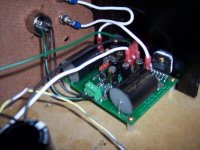
We have noise going in one end and out the other! In other words, nothing is blowing up. Which is better than nothing, to be sure.
I'm currently running this with single ended input, I- shorted to ground. I have one of the TP X-BOSOZ kits needing assembly, but that takes time and I wouldn't want to test a brand new amp circuit with it anyhow.
On each side of the circuit is a LM4780, paralleled.
It's rather quiet, and past a certain input level, the sound seems to go all to crap. The quiet issue I am currently attributing to my use of a 100K log pot (cheap unit from Radio Shack, but does a great job when testing things that might blow up still) and the need for more current but I'm not 100% sure this is what's up. Off a CD player (portable) I don't get distortion, but it never gets very loud at all. Off an old portable "boom box" using the headphone out to the pot, it gets much louder but immediately goes to crap sound-wise past that certain level.
Rail voltage is slightly high, about 31.6V. I want to bring that down a couple V. Regulated, clearly. Figured I'd walk through a step at a time, and for testing the PCB's and whatnot so far, so good.
Q3 is getting very toasty - I can touch it for a second or so and that's it. Is this normal?
Chips (amp) are cool to the touch.
I've read back through the thread, but am not really sure where to start as far as trying to isolate where my issue lies.
I am using the latest schematic, even though it came out after I ordered my boards. 🙂 Had to surface mount a couple compact resistors, but it worked out just fine.
C
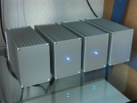
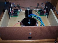
SuSy amp up and running
First stereo prototype in my ugly prototype case is up and running and sounding excellent. No DC offset and no bad habbits to be seen yet. The music sounds, well great!!! 🙂
Note, I did not use the zobel, partly because my speakers are an easy load, and partly because of a design oversite which would have made them hard to fit on the PCB. Good thing these are prototype PCBs. The final PCBs will have several enhancements based on things learned from the prototype.
The power supply is unregulated and powered by a 2 x 20V 500VA trafo.
A special thanks to Ed for the PCBs. And a toast to Terry for his excellent work and incredible support. Of couse thanks to Nelson Pass for sharing the idea with us.
I will post more details later, but for now here is a picture.
Attachments
nice!
I wish I could say mine worked as well. 😉
I think I'm going to have to just post up a link to files here since e-mail is giving me fits. Must be blocked at the server.
C
I wish I could say mine worked as well. 😉
I think I'm going to have to just post up a link to files here since e-mail is giving me fits. Must be blocked at the server.
C
C,
I am getting your email. I am not sure why you aren't getting mine. Do you have another account? If you do email it to me and I will respond to you there.
Cheers!
Russ
I am getting your email. I am not sure why you aren't getting mine. Do you have another account? If you do email it to me and I will respond to you there.
Cheers!
Russ
Thats good news🙂First stereo prototype in my ugly prototype case is up and running and sounding excellent.
Great work, Russ and Terry🙂
Steen😎
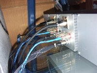
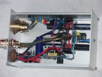
One channel of mine is ready for turn on too maybe this evening if have enough time :
Regulated PSU with per monobloc : 300Va 2x25V, 15000+6800µF per rail, snubbers are present too
Marc
An externally hosted image should be here but it was not working when we last tested it.
An externally hosted image should be here but it was not working when we last tested it.
An externally hosted image should be here but it was not working when we last tested it.
An externally hosted image should be here but it was not working when we last tested it.
Regulated PSU with per monobloc : 300Va 2x25V, 15000+6800µF per rail, snubbers are present too
Marc
Wow... seems a whole bunch of us are getting working PCB's going here. 🙂
I sent a note to Russ on this but I'll ask more generally:
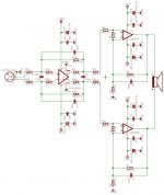
In Terry's schematics, he has a 10kR on the chip input and a 625R to ground after that 10k. Reading over the datasheet and some other posts around here on troubleshooting, I am wondering if this is a mix-up and that 10kR should be to ground, the 625R to input (with the 10k to ground before the 625 to input).
This one my PCB's can actually handle, no surface-mounting or otherwise hacking it in - since this is how the circuit usually works I had spots for this resistor to ground on-board already.
Also, are any changes required for a 31.6V rail? It doesn't really look like it, but I want to try to eliminate the parts that I'm not quite sure about.
I'll have to try to snap some pics of the mess that is my amp later, but I'm not sure I should. It's lots of clamps holding chips to heatsinks right now. 😉
C
I sent a note to Russ on this but I'll ask more generally:
In Terry's schematics, he has a 10kR on the chip input and a 625R to ground after that 10k. Reading over the datasheet and some other posts around here on troubleshooting, I am wondering if this is a mix-up and that 10kR should be to ground, the 625R to input (with the 10k to ground before the 625 to input).
This one my PCB's can actually handle, no surface-mounting or otherwise hacking it in - since this is how the circuit usually works I had spots for this resistor to ground on-board already.
Also, are any changes required for a 31.6V rail? It doesn't really look like it, but I want to try to eliminate the parts that I'm not quite sure about.
I'll have to try to snap some pics of the mess that is my amp later, but I'm not sure I should. It's lots of clamps holding chips to heatsinks right now. 😉
C
C,
I think you problem is being caused by the low input impedance of the SuSy chipamp. It is only around 2K.
If you are feeding it through a 100K pot the output impedance of the pot will be way too high for a large portion of the pot travel.
Two ways to fix this:
1) Use a low constant output impedance attenuator like the JT (750 ohms by default). Which should suite the SuSy amp just fine.
2) Use a buffer after your 100K pot.
Cheers!
Russ
- Home
- Amplifiers
- Pass Labs
- GC SuperSymmetry