Kari/Terry
One channel (based on the old schematic) is up and running.
Rail voltage during operation is about 35,5V.
The sound is OK at low levels. I hope the new resistor pack will solve the dist problem at higher volumes. Will fix that next week. I also added four 1000uF//100n to each chip.
Cheers and have a lovely weekend,
Vit
Kari,
For CAD I am using MS Visio (just a great general purpose drawing program).
For simulation I am using the feeware LTSpice from Linear Technology. It is pretty basic, but it does everything I have found a need for.
Cheers, Terry
For CAD I am using MS Visio (just a great general purpose drawing program).
For simulation I am using the feeware LTSpice from Linear Technology. It is pretty basic, but it does everything I have found a need for.
Cheers, Terry
metalman said:Kari,
For CAD I am using MS Visio (just a great general purpose drawing program).
For simulation I am using the feeware LTSpice from Linear Technology. It is pretty basic, but it does everything I have found a need for.
Cheers, Terry
I'm planning on using 5687 tubes as the frontend for the susy gc instead of the transistor one. As soon is i get my spice running (probably Target3001!) and finish my "studies".
Voltage for the front end and for the GC chips should really be separated. To much hassle with that don't you think?
/Kari
Hi all,
I've used the ECC86/6GM8 as input stage/phase splitter/feedback
input (same as the transistors you propose to replace with a valve)
for a bridged chip amp, very closely resembling an X amp. (I only
just read this thread, and discovered that I'd "accidentally" built a
SuSy!). It uses paralleled/bridged LM1875 chips. Works a treat.
The ECC86 can comfortably run off the same rails as the chips
(Vak max = 30V!). This is probably the best sounding amp I've built
so far (which perhaps isn't saying sooo much - it's only my 5th
power amp - though 7th design; I've yet to finish those darn
OTLs...).
Of course, the 5687 would work well too, but it would need more
voltage to do its best. An advantage that the ECC86 holds is its
very low input capacitance, although this isn't so relevant in the
standard X configuration, with low Zin. However, another half
ECC86 could serve as a concertina (split triode) phase splitter at
the input before everything else. Then, any preamp could easily
drive the amp; or a volume control of almost any value could be
added on the input to make it an integrated.
I'm guessing about 3mA idle would be a suitable current for the
ECC86 sections (with about 20V across the valve and 20V across
the anode resistors).
If a concertina is used on the input, the diff. stage input resistors
and feedback resistors would have to be trimmed up to a few
kilohms in order not to load the ECC86 so severely. But the same
is probably true for the 5687. With the low input and Miller
capacitances of the valves, this should not be a problem.
Just thought I'd tell you about this alternative. Anyway - happy
building!
Morgan
Ipanema said:Hi Kari,
Can eagle import library from Protel?
Thanks.
No, i don't beleive it does.
/Kari
I've desided to go with Protel DXP. Maybe someone has any libraries/spice models for tubes?
/Kari
/Kari
I've changed the resistors on one channel. Power on....ZAP 
Now I have 15 ohms between +V and -V. And I cant't find the reason.
Now I have 15 ohms between +V and -V. And I cant't find the reason.
Hello Vit some news? Have you found why the chanel Zap. Have some one other done the modifications? I haven't time yet to go forward in the project.
Marc
Marc
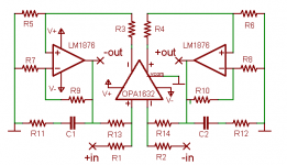
buffer opa 1632
what about additional buffer (opa1632) for unbalanced mode ? for preserve supersymetry advantages
what about additional buffer (opa1632) for unbalanced mode ? for preserve supersymetry advantages
One more vote for the LM4780.
How are the plans to make these a groupbuy? What about making this a compleate kit?
I think that there should be an optional add on board to make SE into balanced in the GB. This way you could put a XLR and an RCA for each chan. and add a switch so you could use either a SE or balanced preamp.
How are the plans to make these a groupbuy? What about making this a compleate kit?
I think that there should be an optional add on board to make SE into balanced in the GB. This way you could put a XLR and an RCA for each chan. and add a switch so you could use either a SE or balanced preamp.
SuSy chipamp PCBs available soon
Hello all,
I am very pleased to anounce the arrival very soon of PCBs for DIY use of Terry's SuSy circuit. Terry (metalman) has graciously given Brian and I permission to provide this circuit to DIY users by selling PCBs and Kits for DIY use only at Twisted Pear Audio.
My plan is to start with a dual LM3886 monobloc PCB first, and then soon after a single LM4780 monobloc. Eventually I may also provide a dual LM4780 monobloc with the LM4780s in parallel arrangement.
I will post details of the PCBs as they arise, and I don't expect it to take very long, as I have already produced a single side layout for this amplifier which worked quite well some months back. The production PCBs will be 2 sided.
The PCBs will be available alone, or as a complete parts kit + PCB from Twisted Pear audio.
Brian and I are humbled by Terry's support, and the support of the DIY community at large.
I expect PCB prices to be in the $12-15 range per monobloc channel and kit prices will have to be determined later, but the price will be based on our actual cost plus operating costs, we have no ideas of commercial application or large profit margine, we are very much just DIY hobbiests who want others to be able to build what we are building on a regular basis. Often times people miss out on great circuits because they could not get in on a group buy in time for whatever reason, by keeping these in stock we hope to avoid that situation.
Cheers!
Russ
Re: SuSy chipamp PCBs available soon
Very interested in that one... transformers & chassis ready to go...
dave
Russ White said:a single LM4780 monobloc.
Very interested in that one... transformers & chassis ready to go...
dave
My plan is to start with a dual LM3886 monobloc PCB first, and then soon after a single LM4780 monobloc. Eventually I may also provide a dual LM4780 monobloc with the LM4780s in parallel arrangement.
Hello Russ,
Does LM4780 in paralle have the new schematic? Or can it just use Terry's resistor values in 3886? I want a try on that ...Thanks🙂
DANS
Originally posted by Dans
Does LM4780 in paralle have the new schematic? Or can it just use Terry's resistor values in 3886? I want a try on that ...Thanks
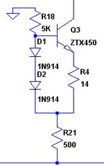
It was discovered that my last posted schematic values drives the CCS transistor at an excessive power level. The solution is to add another resistor in series beteen the CCS and the negative rail to reduce the voltage drop acros the CCS. I have provided the Twisted Pear guys with an updated schematic, but I don't have it at hand right now. I'll post the specific correction when I get a chance.
As to the LM4780, I have tried that yet, but my off-the-cuff thought is that it should be possible to directly substitute the 4780 for the pair 3886's.
Cheer, Terry
metalman said:
It was discovered that my last posted schematic values drives the CCS transistor at an excessive power level. The solution is to add another resistor in series beteen the CCS and the negative rail to reduce the voltage drop acros the CCS. I have provided the Twisted Pear guys with an updated schematic, but I don't have it at hand right now. I'll post the specific correction when I get a chance.
Cheer, Terry
Could you explain more, i do the last change you gave us. I think you are speaking over R16, for moment I place à 12R4 for 26-28 rail voltage.
Marc
Marc,
This is the change I mentioned. The values I provided for you will work, but the ZTX450 is running close to it's 1W maximum rating. The part number of this figure may be off from my previous schematics (I did a quick copy from a spice model I use), but it is a pretty simple change so I don't think this will cause too much confusion.
Cheers, Terry
Attachments
- Home
- Amplifiers
- Pass Labs
- GC SuperSymmetry