Thx,
the idea here is that the gnd @ the pwrsupply is stargnd for all gnd connections. I'll let you know how it works out.
/Kari
the idea here is that the gnd @ the pwrsupply is stargnd for all gnd connections. I'll let you know how it works out.
/Kari
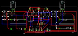
It's so long time I didn't make any audio amplifier because I was so busy. However, I have already made GC Supersymmetry PCB. For my XGC, I apply LM1875T in my board it's cause IC chip cost is so cheap. Could anyone help me review it correct or not? Thanks a lot for helping.
Attachments
Kari,
> Here's a pic of a protopcb i made for the above schematic
A pity that you shy away from showing us your excellent work on the bottom (non-component) side.
Patrick
> Here's a pic of a protopcb i made for the above schematic
A pity that you shy away from showing us your excellent work on the bottom (non-component) side.
Patrick
mikelm said:
I think the leading issues might be
Infinite gain
zero i/p impedance
How do you drive that ? ...
I can't speak to "inifinite gain", but as for (near) zero input impedance, you'd be better off driving it with a current source.
As a voltage source enjoys driving a high input impedance, a current source digs a low input impedance.
Originally posted by EUVL
A pity that you shy away from showing us your excellent work on the bottom (non-component) side.
I think he did. I believe the red traces are top layer, and blue traces indicate the bottom layer.
Cheers, Terry
EDIT

 I need to pay better attention, cause I posted before I realized that you were referring to Kari's board and not Gencard's. Sorry for the confusion!
EUVL said:Kari,
> Here's a pic of a protopcb i made for the above schematic
A pity that you shy away from showing us your excellent work on the bottom (non-component) side.
Patrick
Well here it is:
An externally hosted image should be here but it was not working when we last tested it.
Kari,
Absolutely beautiful pcb work! You have infected me with pcb envy! It think your XGC will be the best version produced yet. I can't wait for you to put it all together and hear your thoughts on it. Also, please keep the pictures coming.
Cheers, Terry
Absolutely beautiful pcb work! You have infected me with pcb envy! It think your XGC will be the best version produced yet. I can't wait for you to put it all together and hear your thoughts on it. Also, please keep the pictures coming.
Cheers, Terry
Hi Kari,
It's a beautiful PCB board. How about your XGC sound?
I'm now improving my PCB after I saw Kari's PCB. I have to rearrange components.
It's a beautiful PCB board. How about your XGC sound?
I'm now improving my PCB after I saw Kari's PCB. I have to rearrange components.
Kari,
Very nice layout.
One suggestion if I may. I would put the two diff-pair transistors closest to each other so that they can be thermally coupled to minimise difference in thermal drift.
Or better still, use a matched dual like LM394 or MAT02 in a monolithic metal can.
Are you using LM3875 or LM3886 on your layout ?
If I remember correctly, it has been mentioned that LM3886 should sound better because of less open loop gain.
Patrick
In Kari's post (#419) he referenced agent.5's schematic (post #414), which uses the LM3886 chip. I would assume that Kari is also using the LM3886 chip(s).
gengcard said:It's so long time I didn't make any audio amplifier because I was so busy. However, I have already made GC Supersymmetry PCB. For my XGC, I apply LM1875T in my board it's cause IC chip cost is so cheap. Could anyone help me review it correct or not? Thanks a lot for helping.
Go to the National homepage and register yourself there. Then request for LM3886 samples, you can request max 5 pcs. I did that and i received them in 2 weeks.
/Kari
Hi,
i completed 2 channels this weekend. I used 2 150VA 2x18V trafos and 4 10000uF filtercaps. Otherwise nothing special, the 1 uF and 0,1uF caps used are polyprops, resistors 1% metalfilm and the electrolytics are standard. No heatsink was used, instead i bolted the chips directly to the case.
Unfortunantley my preamp couldn't deliver enough current because of the low impedance input of the xgc so i could crank up the volume only so far. I also used singleended inputs. Hopefully my x-boz is finished until next weekend so i can make a proper eval.
So far it sounds pretty good altho i feel that it sounds different compared to my Mini-A, but i have to return with the sound eval later.
I spent around 150USD on this amp and for that kind of money there isn't anything in the market that can compete.
/Kari
And here's a couple of pics:
/Kari
An externally hosted image should be here but it was not working when we last tested it.
An externally hosted image should be here but it was not working when we last tested it.
/Kari
- to GND.
I have completed my x-bosoz so i will use balanced input on the xgc. However my daugter managed to trash the sled on my current player so i cannot test until i get a new one.
/Kari
I have completed my x-bosoz so i will use balanced input on the xgc. However my daugter managed to trash the sled on my current player so i cannot test until i get a new one.
/Kari
my daughter managed to trash the sled
God bless the child, they are the world to all of us
Kari, I think it is so igenious of you to flip one chip over, and so by doing, retain the "symmetry" of traces on board.

What is your experience in using 2 bridges /channel? Can you "hear" a difference?
New Changes!!!!
OK, you guys are going to kill me
I had a get together last Friday night with an audiophile friend of mine. We were originally going to audition my completed Aleph-X monoblocks, but as it turned out that they were not quite complete, I took over my XGC (GC Susy) amp in their absense. I live in a condominium with my wife who isn't fond of overly loud music, whereas my friend lives in a house with a dedicated audio room and his wife wasn't going to be home, so I was looking forward to listening to my XGC without having to apply the usual restraint.
We listened to a few tracks on his system, into which my friend had recently added a Linn Unidisk player that I hadn't yet heard, and then switched in the XGC. We listened to the same few tracks at moderate lsitening levels, and it sounded very good. Next we got out some rock music suitable for PLAYING REAL LOUD, but with the volume turned up everything got real muddy, the soundstage had completely collapsed, it sound quite awful. We turned the volume down from REAL LOUD to just Loud and the sound quality came back. We assumed that we had pushed the amp into clipping, but we were unsure because his speakers don't present a particularly nasty load to the amplifier, and we didn't think we had pushed the amp hard enought that it should have clipped.
So over the weekend I spent some more time at home testing the testing the amp, comparing the test measurements against a spice model, and then took the amp to work where I have access to a scope and other diagnostic tools.
This is where you guys aren't going to like me very much! What I discovered is that while the op-amps weren't being pushed into clipping, there was sufficient gain on the input differential pair that the bipolar transistors were being pushed into clipping when the amplifier output hit ~3V, or 1W into my 8 ohm speakers, or 2.25W into my friends 4 ohm speakers. This correlated pretty well with our listening observations at my friends place, where we figured we could get about 80-85 dB before things got ugly.
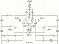
So, I've redesigned and retested, and I'm confident I've fixed this rather ugly screw-up. The topology remains unchanged, and with the exception of one resistor, the alterations consists simply of swapping in some different resistor values. The new schematic is below, and the changes are as follows:
R1, R2, R11, R12 now = 500
R7, R8 now = 100k
R9, R10 now = 625
R16 now = 14
R15 now = 250, minimum 1/2W rated, preferrable 1W
The major effects of the changes are that the amplifier gain is now ~30dB (increase of 10dB), the bias current for the differential pair has increased by ~5X, global feedback has been reduced by 6dB, the gain of the input differential has been reduced by ~12dB, and the amount of gain that has to be "thrown away" is ~9dB less.
I feel pretty sheepish about this, and I can't believe that neither I or any of the other builders of this circuit had discovered this before. I guess Nelson's statement about the first watt being the one that matters really is the case!
Finally, I'd like to encourage the more competent designers amongst us to check my work, and see if I have anything else lurking in the design that I haven't discovered yet.
 Terry
Terry
OK, you guys are going to kill me
I had a get together last Friday night with an audiophile friend of mine. We were originally going to audition my completed Aleph-X monoblocks, but as it turned out that they were not quite complete, I took over my XGC (GC Susy) amp in their absense. I live in a condominium with my wife who isn't fond of overly loud music, whereas my friend lives in a house with a dedicated audio room and his wife wasn't going to be home, so I was looking forward to listening to my XGC without having to apply the usual restraint.
We listened to a few tracks on his system, into which my friend had recently added a Linn Unidisk player that I hadn't yet heard, and then switched in the XGC. We listened to the same few tracks at moderate lsitening levels, and it sounded very good. Next we got out some rock music suitable for PLAYING REAL LOUD, but with the volume turned up everything got real muddy, the soundstage had completely collapsed, it sound quite awful. We turned the volume down from REAL LOUD to just Loud and the sound quality came back. We assumed that we had pushed the amp into clipping, but we were unsure because his speakers don't present a particularly nasty load to the amplifier, and we didn't think we had pushed the amp hard enought that it should have clipped.
So over the weekend I spent some more time at home testing the testing the amp, comparing the test measurements against a spice model, and then took the amp to work where I have access to a scope and other diagnostic tools.
This is where you guys aren't going to like me very much! What I discovered is that while the op-amps weren't being pushed into clipping, there was sufficient gain on the input differential pair that the bipolar transistors were being pushed into clipping when the amplifier output hit ~3V, or 1W into my 8 ohm speakers, or 2.25W into my friends 4 ohm speakers. This correlated pretty well with our listening observations at my friends place, where we figured we could get about 80-85 dB before things got ugly.
So, I've redesigned and retested, and I'm confident I've fixed this rather ugly screw-up. The topology remains unchanged, and with the exception of one resistor, the alterations consists simply of swapping in some different resistor values. The new schematic is below, and the changes are as follows:
R1, R2, R11, R12 now = 500
R7, R8 now = 100k
R9, R10 now = 625
R16 now = 14
R15 now = 250, minimum 1/2W rated, preferrable 1W
The major effects of the changes are that the amplifier gain is now ~30dB (increase of 10dB), the bias current for the differential pair has increased by ~5X, global feedback has been reduced by 6dB, the gain of the input differential has been reduced by ~12dB, and the amount of gain that has to be "thrown away" is ~9dB less.
I feel pretty sheepish about this, and I can't believe that neither I or any of the other builders of this circuit had discovered this before. I guess Nelson's statement about the first watt being the one that matters really is the case!
Finally, I'd like to encourage the more competent designers amongst us to check my work, and see if I have anything else lurking in the design that I haven't discovered yet.
TerryAttachments
Dear Terry,
Do you think if we parallel two LM3886 first or even more and then bridge will help the "LOUD" problem ?
It is because your friend's speaker is 4 ohm.
Now I am thinking use "inverting" input so that I can adjust the "DC Offset". What do you think and please comment !
Thomas
Do you think if we parallel two LM3886 first or even more and then bridge will help the "LOUD" problem ?
It is because your friend's speaker is 4 ohm.
Now I am thinking use "inverting" input so that I can adjust the "DC Offset". What do you think and please comment !
Thomas
- Home
- Amplifiers
- Pass Labs
- GC SuperSymmetry