This isn't exactly a budget amp any more (which is still half the draw of chip-amps I think) is it. 
egads.
I mean, not expensive if it's everything it's cracked up to be, but not cheap. That's what I get for having nothing lying around of use to me here!
Ahh well. If it fails, as long as I don't go blowing stuff up I can always use the components elsewhere, maybe. 🙂 Say, a multi-channel amp for my HT or something. If I can clear this purchase with the boss - I'll have to catch her in a good mood.
C
metalman said:Change R9/R10 to 220 ohm to get 26.5dB gain (down from 32dB). According to the sims this should iron out the brightness to a fair degree.
Ok I did it, 1µF foil plus lowered gain with 220R. It seems to me that suddenly this is a very nice amp.
The highs are very clean, the bass very dry.
I may be completely misled by my expectations, but I think you should try it
m.
dieringe, 😀 😀 😀 😀 😀 😀 😀 😀
This is fabulous news. I'm glad and relieved to hear that your problems have finally been sorted out. I was feeling a little guilty for the effort you have put in to try my circuit and end up with a less than satisfying result. It's been a bit of a process to reach a happy result, but then again, I believe this is why it's called DIY.
I fully intend to implement the further gain reduction in my amp before the weekend is out. Thanks for participating and adding your experiences to the continuing evolution of this design.
Cheers, Terry
Would this not be the right time to post an updated schematics ?
With sincere thanks in advance.
Cheers,
Patrick
With sincere thanks in advance.
Cheers,
Patrick
dieringe said:Ok I did it, 1µF foil plus lowered gain with 220R. It seems to me that suddenly this is a very nice amp.
The highs are very clean, the bass very dry.
😀
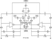
Updated Schematic for a paralleled version, and a simple schematic for a buffer and single sided to balanced circuit if you need/want that part. I think this should take care of any lower powered source straight into this circuit.
Obviously, other buffers exist. This one is simple and uses parts common to the rest of the circuit, which is why I went this route. Those that have other preferences will have no trouble using a different circuit here. 🙂


C
Obviously, other buffers exist. This one is simple and uses parts common to the rest of the circuit, which is why I went this route. Those that have other preferences will have no trouble using a different circuit here. 🙂
C
Carlos:
It would be nice to use the same film/foil 1µF cap used in the main amp circuit to keep things stupid simple...
The buffer schematic is one supplied by Nuuk here and specifies >2.0µF - I believe he used 4.7µF. However, the value is actually there because I neglected to even address that value after a copy/paste. There are a couple things I did in that circuit like that. 🙄 I'll have to fix it.
However, truth be told I don't know. My understanding is that too big won't hurt any but when it comes to calculating proper values I'm never confident that I'm anywhere close.
Of course, use a proper pre with balanced outputs and you don't even need that circuit.
Gotta see if I can get into one of the fall classes locally and get some genuine education or something on this stuff.
C
cjd said:Carlos:
It would be nice to use the same film/foil 1µF cap used in the main amp circuit to keep things stupid simple...
In that case, change R5 for 47k.
cjd said:There are a couple things I did in that circuit like that. 🙄 I'll have to fix it.
Well... 0.47uf followed by a 100k resistor to ground makes a high-pass filter at 9.95Hz.
Just fine to effectively remove DC.
A 4.7uf cap there doesn't do anything.

Nuuk should know better, no? 😉 heh. Thanks! Schematic updated (so everyone will wonder what the heck we're talking about now).
C
C
cjd said:Nuuk should know better, no? 😉 heh.
He knows, but you didn't understand his circuit and it's purpose.
On your application you have 100k to ground and then the chip.
On Nuuk's schematic I see a standalone buffer which will serve to be connected to an inverting power op-amp with lower impedance.
Nuuk's schematic is fine.
Your schematic is fine now too.🙂
You're right - I didn't understand. Still don't. You've given me something to go research now. 🙂 Because now I know there is something more for me to understand.
I *really* need to get to some classes. 🙂
Till then, thank you again! You're always courteous, always helpful. 😎
Now, how to convince my better half to let me pick up the parts I need!
C
I *really* need to get to some classes. 🙂
Till then, thank you again! You're always courteous, always helpful. 😎
Now, how to convince my better half to let me pick up the parts I need!
C
Made the change over to the 220R resistors last night and spent most of today listening to the result. In my amp the change was a little more subtle, I suspect because I was already using film caps compared to dieringe. That being said, the change is quite positive. The tonal balance shifted towards the midrange, and the imaging, which was already good, took another step away from being two dimensional towards having greater image depth. It also maintains better image coherency when the soundscape is densely layered.
Best of all, my wife clearly heard the difference, which tells me that its not just my imagination. For those who are interested, on Monday I'll post the revised schematic.
Cheers, Terry
Best of all, my wife clearly heard the difference, which tells me that its not just my imagination. For those who are interested, on Monday I'll post the revised schematic.
Cheers, Terry
metalman said:Best of all, my wife clearly heard the difference...
That's important

Women are good listeners.

Women are good listeners.
Sure are! (except when we're trying to explain WHY we need to build another one of these "things"). I use that as my barometer for success. When SHE notices (without me saying something, of course) it's real. Last set of speakers I built, she noticed that she could actually HEAR the quiet parts of "The Planets" even when the volume was down (~65dB peaks, so the speakers were resolving 40dB quiet sections clearly). It used to disappear completely.
I had a ponder on this DRV and whatever circuit it is I've put together - will it actually do what it is intended to do? I know the DRV134 will split a signal into a balanced signal - the question is, will the circuit in front of it take care of providing enough drive if a source is plugged in directly (since metalman found that to be insufficient)? Or am I being dumb, and should be putting the circuit on each leg of the DRV *output* (between the DRV and the amp circuit)?
C
cjd said:will the circuit in front of it take care of providing enough drive if a source is plugged in directly (since metalman found that to be insufficient)?
Sufficient or not, that depends on your source.
Most CDPs have "high" output impedance (hundreds of ohms, like 400~500 ohms).
Change those series output resistors for something around 50 ohms and btw remove the muting transistors and with this alone you have quite big improvements.
And then it's driving abilities will be much greater too.
Originaaly posted by cjd
I know the DRV134 will split a signal into a balanced signal - the question is, will the circuit in front of it take care of providing enough drive if a source is plugged in directly (since metalman found that to be insufficient)?
Keep in mind that my earlier comment about needing some current drive was based on connecting the output of my Toshiba mass market CD player to the XGC through a 20K series attenuator.
A good rule of thumb is that the output impedance of a source device should be at least 10x less than the input impedance of the device being driven. The XGC input impedance is low, around 2K. If you use Carlos' example you have 500R output impedance driving a 2K input impedance through a series attenuator, which divides the current before it goes into the XGC, leaving a less than optimal arrangement.
Ipanema asked me earlier about the DRV134, and the answer was that the data sheet says it can output 7Vrms into a 600ohm load, indicating a slightly more than 100R output impedance. This gives a 20:1 ratio of input to output impedance,which should be more than enough drive for the XGC.
Cheers, Terry
So just a DRV134 would be sufficient I take it?
I'm not sure what my final setup will be, and I'm sure other folks out there may want to try this. I won't be able to drive it balanced currently without at least the DRV since I definitely have nothing in the house that outputs a balanced signal (well, except for my mic and the mixer that goes with that.)
I currently am using a standard GC with an external attenuator. So, that's the likely place for this amp to get inserted for testing. 🙂
Regardless, I feel I need to understand a little better what's going on before I dive in on this one. More reading for me. 🙂
C
cjd said:So just a DRV134 would be sufficient I take it?
Hi
There is a better chip than DRV134 to split signal into balanced mode – OPA1632 also from TI 😉 I’m using this one as a driver in balanced/bridged GC application. It can drive a low impedance inputs 🙂
opa1632 application
opa1632 dataseet
An externally hosted image should be here but it was not working when we last tested it.
- Home
- Amplifiers
- Pass Labs
- GC SuperSymmetry