Re: I got the results from the circuit
Hi GenCard, do you have a spice model for the lm3875? can you share it with me?
Thank you!
gengcard said:I tried to simulate the circuit by Pspice ...
Hi GenCard, do you have a spice model for the lm3875? can you share it with me?
Thank you!
do you have a spice model for the lm3875? can you share it with me?
Sorry Faber, I don't have it. However, I tried OPA541 in my gainclone simulation by Spice. I'm really want LM3875 spice model too.

veteran said:->Nelson Pass
Did you tried the opa1632? It's a fully differential, fast and hi output power op-amp and it sounds great. Gain of opa1632 i set at 2V/V and LM3875 at 10V/V.
No, I haven't tried it, and probably will never have the time to.
Getting Closer
I had hoped to be posting some comparisons between the standard GC and a SuSy GC today, but it will have to wait a few more days yet. Over the weekend I completed the Susy circuits, wired the input and output connectors and connected it to my GC power supply.
When I fired it up and took a few measurements I very quickly realized I had made an A$$ of myself by forgetting something very fundamental.😕 😱 🙄
The LM3875's have a very high PSRR, so 1500uF between each rail and ground for each chip provides a quiet enough supply for them. The same cannot be said for the differential pair of bipolar resistors in the SuSy GC where the large amount of PS ripple (roughly 10-20 mV) wreaks havoc.
So DigiKey to the rescue, and my order for some BIG capacitors and parts to build some high current low output impedance voltage regulators should arrive tomorrow afternoon.
I promise I will get there eventually!
I had hoped to be posting some comparisons between the standard GC and a SuSy GC today, but it will have to wait a few more days yet. Over the weekend I completed the Susy circuits, wired the input and output connectors and connected it to my GC power supply.
When I fired it up and took a few measurements I very quickly realized I had made an A$$ of myself by forgetting something very fundamental.😕 😱
🙄 The LM3875's have a very high PSRR, so 1500uF between each rail and ground for each chip provides a quiet enough supply for them. The same cannot be said for the differential pair of bipolar resistors in the SuSy GC where the large amount of PS ripple (roughly 10-20 mV) wreaks havoc.
So DigiKey to the rescue, and my order for some BIG capacitors and parts to build some high current low output impedance voltage regulators should arrive tomorrow afternoon.
I promise I will get there eventually!
I'm working on OPA1632 and OPA541 amp. I've already made a PCB and in few days time I'm going to test it.
I need to listen the sound of design. 😀 Please write down in this thread when it's finished.
I'm working on OPA1632 and OPA541 amp.
The input impedance seems to be 1k. This won't work well with the 10nF C4.
Is this close to a working schmeatic? Also, does this amp heat up as much as say an Aleph?
Thanks,
Vince
Thanks,
Vince
kafka said:I'm working on OPA1632 and OPA541 amp.
Good and bad news... The amp works... And the bad: Not too long, cos I had an accident and burnt one of the OPA541 and my speskers too 🙁 35V DC... But I have noticed that the offset before an accident was about 1V <wow> Maybe I'll stat thinking about an intergrator... and DC speakers protection...
Better than me!
Yours worked longer than mine. Congrats on that and my condolensces on your accident. I guess misery loves company, though, as last night, while excessively over-tired and being excitedly encouraged and assisted by a very impatient friend, I completed the addition of voltage regulation to my power supply, and performed a couple quick measurements to confirm it was working. Then, quite foolishly, I allowed myself to be pursuaded into rushing the connection to the amp circuits for a quick listen before it got too late 🙄.
I flipped the switch and watched the lights momentarily dim as the slo-blo fuse blew . I held my breath frantically hoping that the fuse was the only thing that blew, as I didn't hear anything pop and there wasn't any smoke or sparks, but I wasn't that lucky. Don't know about the amp circuits, but the rectifier bridges and voltages regualtors are toast . Won't know about the amp circuits until I get the PS rebuilt
  .
.
Yours worked longer than mine. Congrats on that and my condolensces on your accident. I guess misery loves company, though, as last night, while excessively over-tired and being excitedly encouraged and assisted by a very impatient friend, I completed the addition of voltage regulation to my power supply, and performed a couple quick measurements to confirm it was working. Then, quite foolishly, I allowed myself to be pursuaded into rushing the connection to the amp circuits for a quick listen before it got too late 🙄.
I flipped the switch and watched the lights momentarily dim as the slo-blo fuse blew
. I held my breath frantically hoping that the fuse was the only thing that blew, as I didn't hear anything pop and there wasn't any smoke or sparks, but I wasn't that lucky. Don't know about the amp circuits, but the rectifier bridges and voltages regualtors are toast . Won't know about the amp circuits until I get the PS rebuilt .After a long hiatus from DIY'ing I finally got back to working on this project over the last couple of weekends. I built a new regulated power supply, hooked up the amplifier circuit leaving the inputs disconnected (i.e. floating) and turned on the power. There was between 1 an 2V of DC offest at the outputs, so I tried again after connecting the inputs, positive and negative, to ground. This time there was 10mV DC in the left channel ouputs and 25mV on the right. I only have my multimeter as a diagnostic tool, so I hooked up some old speakers and had a listen. There was hiss from both channels at the loudness of a quiet conversation, and the right channel had some hum that was just audible when standing a few feet away from the speaker.
Next I measured the voltages across various components in the circuit, and they were more or less the same as the spice model predicted. One strange thing happened while I was doing the measurements. If I measured the collector to base voltage on any one of the BJT's in the differential pairs, as soon as the probes were connected the hiss and hum dropped to very low levels in both channels, even though I was only measuring one BJT from the differential pair in one channel.
Obviously I have some stability issue that is causing oscillation in the circuit, but I am not entirely sure what to do about it. At this point my plan is to sleep on it overnight, and if no-one has any better suggestions I'll try adding a bit of capacitance between the collector and base of each BJT and see what happens. On the other hand, suggestions are most welcome.
One last thing, but I don't think this is the source of my troubles. I cheaped out and am using ZTX450's instead of MPSA18's. I know they are more noisy than the MPSA's but I thought for prototyping purposes they would be OK.
Terry
I expect that you would encounter stability issues with such
a topology due to the very high open loop gain of the chips.
I doubt that the choice of NPN bias transistor has much to do
with it.
I suggest you start by "throwing away" open loop gain in the
manner described by the first of the "Seven Easy Pieces" thread.
😎
a topology due to the very high open loop gain of the chips.
I doubt that the choice of NPN bias transistor has much to do
with it.
I suggest you start by "throwing away" open loop gain in the
manner described by the first of the "Seven Easy Pieces" thread.
😎
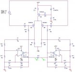
Really??? It's a good news for me 😀Looks good enough to me.
Yesterday, I tried to simulate this schematic again and it's indicated a fair result. I'm wanderring why I got the different results from the same schematic 😕 Maybe I must check the simulated software (Pspice) again.
- Home
- Amplifiers
- Pass Labs
- GC SuperSymmetry