
Actually, maybe you could then swap that resistor with the feedback cap and orient it so that the gound end is down. Would look goofy.
Russ White said:Hi N00ber,
I think you can safely ditch the BW resistor. I have been listening for a few days now, and do not miss it. Really as long the the buffer is heatsinked it is not necessary (I probably should not have mentioned it).
I wonder if you could turn that one decoupling cap on V+ at the buff 90 degrees do that it is oriented up and down. then move the electrolitic over to the right slightly. Viola, no more island (at least not one that matters), and no jumper.
It won't look quite as symmetrical, but who cares?
I was thinking of that myself but i just keep seeing carlos' suggestions and his
 gifs evertime i chaage the position of the caps, but is still leaves the resistor isolated.
But i do h8 jumpers more than this suggestion 😉
I may put the caps at an angle but I will sleep on it and see what comes tomorrow.
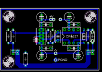
Here is the BW track with smd pads
EDIT: forgot to attach image
Attachments
n00beR said:I was thinking of that myself but i just keep seeing carlos' suggestions and his
😀
The caps are very important, yes.
You don't need the BW resistor, just use a direct connection.
Why limit bandwidth and output voltage swing?
With most modern op-amps you need to use the BUF634 in wide BW mode, no intermediate settings needed.
carlosfm said:
😀
The caps are very important, yes.
You don't need the BW resistor, just use a direct connection.
Why limit bandwidth and output voltage swing?
With most modern op-amps you need to use the BUF634 in wide BW mode, no intermediate settings needed.
That makes me feel a whole lot better 😀
Especially from an experinced builder, such as yourself carlos

thanks
n00beR
carlosfm said:
The caps are very important, yes.
You don't need the BW resistor, just use a direct connection.
Why limit bandwidth and output voltage swing?
With most modern op-amps you need to use the BUF634 in wide BW mode, no intermediate settings needed.
Take a look on Tangent's site regarding the BW limiting resistor for the BUF634. There actually *IS* an optimum value. One of the members of head-fi tested the BUF634 and measured it's noise with various resistances. Here's what Tangent says in the assembly guide of the Pimeta amps:
http://www.tangentsoft.net/audio/pimeta/pguide.html
"The highest useful value for this resistor is about 4.7 KΩ. As the value drops, the buffer's bandwidth and quiescent current draw go up. (The graph "Quiescent Current vs Bandwidth Control Resistance" in the datasheet shows the relationship.) According to tests by KurtW and others, distortion drops as bandwidth goes up, though once R11 falls below about 200 Ω, distortion starts rising again."
Basically, you should set it to ~200 ohms, unless you're stacking the output buffers (which does provide more drive current and increases the slew rate into capacitive loads (due to the buffers sharing the load).
http://www.tangentsoft.net/audio/pimeta/tweaks.html#stack-buffers
Heck, while everyone's at it, would it be possible to add room to have the buffers stacked? With the 5 pin package, it makes it very easy to just put them in line next to each other.
Also, I doubt you will need heatsinks on these things -- I have used the BUF634 into various loads and never even felt them warm up.
Looking at the board in post #663, it seems possible to lengthen the tracks going to E4, the SMD part, so there was room enough for a std. resistor for the BW. Then People can use it or not. I know the nice symmetry will suffer from this, though. If there actually is some advantage to it, just as well put it on the board.
Steen🙂
Steen🙂
dont skimp on the BW resistor.
me wants it in place, since there is a optimal resistance to be had.
stackable buffers aint really needed is it?
-marius
me wants it in place, since there is a optimal resistance to be had.
stackable buffers aint really needed is it?
-marius
I doubt anyone would use that resistor.
Isn't the opamp biased more via the buffer if the BW is shorted or am i wrong? carlos?
Isn't the opamp biased more via the buffer if the BW is shorted or am i wrong? carlos?
It is true that THD and current noise is LESS with some resistance such as 200ohm to BW. The noise floor is indeed lower than with straight wire, but I am not sure is performance is not somehow better in other ways (beside bandwidth) with it shorted. Still it is a confirmed fact that noise and distortion do go up with just wire there. Still, I am happy with my pre and it is shorted at BW.
demogorgon said:dont skimp on the BW resistor.
me wants it in place, since there is a optimal resistance to be had.
stackable buffers aint really needed is it?
-marius
In tangents, morsels and PPLs designs the buffer of choice is usually the BUF634, however this is in DIP8 format.
Dont quote me on this, but I seem to remeber a discussion at some time, on some other forum about the differences between the packages.
The TO220 is better suited to driving higher currents, up to the rated 250mA, due to the fact that it is easy to mount a heatsink to it.
However the DIP8 format does not perform as well towards the 250mA limit.
Hence if you stack the DIP8 buffers the performance will increase.
I have never heard of anyone stacking the the TO220 packages, although I have seen them run in parallel.
Thx
n00beR
motherone said:Take a look on Tangent's site regarding the BW limiting resistor for the BUF634. There actually *IS* an optimum value. One of the members of head-fi tested the BUF634 and measured it's noise with various resistances. Here's what Tangent says in the assembly guide of the Pimeta amps:
http://www.tangentsoft.net/audio/pimeta/pguide.html
I've got really scared when I once saw the pimeta PCB.
With that PSU arrangement and very poor bypassing, I don't take for granted anything they say.
The BW resistor could make a difference, I can't deny it because I didn't test. I just can't see a point of using it.
But there's no harm to include it, as long as you don't have to make concessions to PSU layout.
I also can't see a point of biasing this circuit to class-A.
With that miserable PSU arrangement bass is not tight, detail is not even near to what this circuit can produce.
Then they go paralleling buffers to have "tighter bass".

In my oppinion, paralleling buffers should be avoided, stacking them should be avoided like the plague.
It is not needed for a line preamp, and it is not needed for 99.99% of the headphones.
fully agree with carlos on the stacking part.
Now as for the BW resistor, the design will be more flexible allowing this resistor to be placed. it's not so much of a pain is it?
you could design for it to be placed vertical, thus saving a litle room if thats what's tickeling..
Now as for the BW resistor, the design will be more flexible allowing this resistor to be placed. it's not so much of a pain is it?
you could design for it to be placed vertical, thus saving a litle room if thats what's tickeling..
OK I made a few minor changes to the last PCB I posted, I removed the connections from signal ground to power ground on the bottom layer and instead moved the entire signal ground to the top layer. The only place these two meed is at the ground connection from the PSU. You can see that I put this little beauty together today from the photo, haven't listened to it yet. I was a bit short on mounting hardware, so I will eventually replace those monster screws going to the heatsinks. And no I didn't isolate the chips from the heatsink...and no the heatsink does not come in contact with the signal ground...I "engineered" them just for this board 😉 The in connection is between the two big caps...which are optional, the out is behing the heatsink. I used quick connect headers because I had them and they fit. Oh yeah...ther is also a 0.47uF MKT cap between those big caps on the input. The gain is set to 8....and there is a 120R resistor to set the bandwith mode of the BUF634. 
Comments are welcome. 😀
Comments are welcome. 😀
Attachments
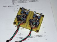
The boards look nice and so is the mounting of BUFs on heat sinks.
It 'd be nice if would post the schematics and layouts to help lamers like me.
Thanks
It 'd be nice if would post the schematics and layouts to help lamers like me.
Thanks
 I like it G!
Hi G, My only comments are that you could make the boards smaller by moving C1 and C2 (which appear as simple filter caps) off this board and onto the PS. Those with well filtered/regulated supplies will not need them. I really like how you did the ground plane, but then that forces you to use double sided boards, which may be of no consequence, but it will slightly increase the cost if we did a GB based on your design. The HUGE power traces are cool! 😎
- Status
- Not open for further replies.
- Home
- Amplifiers
- Chip Amps
- GC Preamp Suggestions