If you really needs some Guineapigs, let me know😉Thats why my OPA134 is gonna be guineapigs.
You are wellcome😀 😀(Thanks steeno!)
Sorry about that one, couldn't help it😀 😀
Steen.😎
Edit: Hate to repeat myself, but it is still Steenoe, not Steeno🙄
Well I maybe good at placing the components symetrical but to say i'm a good designer thats not true. But it's fun to try anyways hehe, as i'm interested in the CAD world were everything is exact.
So... is it a single psu for 2 channels or a dual?
What diodes?
If single psu... then heatsinks to the regs?
What kind of arrangement? C/RC/CRC/RCRC/CLC/PC/MAC or none or..? 😀
So... is it a single psu for 2 channels or a dual?
What diodes?
If single psu... then heatsinks to the regs?
What kind of arrangement? C/RC/CRC/RCRC/CLC/PC/MAC or none or..? 😀
I vote if they are panelized then single supply with 2 channels of preamp on the panel. RC or CRC. 🙂
If we want to offer both boards for the GB then I propose a panel of 2 channels preamps, and a seperate PS board. That will give people who want seperate PS for each channel that option.
If we want to offer both boards for the GB then I propose a panel of 2 channels preamps, and a seperate PS board. That will give people who want seperate PS for each channel that option.
Russ, you seems to know stuff 🙂 if we use my schematics as a starting point
http://www.ettnet.se/~tobias/diy/opabuf/schema_psu.jpg
what would You do different? and everybody else, and don't be shy... that board is in the mail already 🙂
Smaller caps on the end maybe i have heard (1200 ones)
http://www.ettnet.se/~tobias/diy/opabuf/schema_psu.jpg
what would You do different? and everybody else, and don't be shy... that board is in the mail already 🙂
Smaller caps on the end maybe i have heard (1200 ones)
You are pushing it, Tobias😉 The overall best filtering that excists on "God's green earth" is CLC!! No doubt about that! One PSU per channel, heatsinks like the Fischer 2sk104 and a couple of oversized FET's! And you are basically done.. He-he Please ask again tomorrow, I have some more to say😀 😀What kind of arrangement? C/RC/CRC/RCRC/CLC/PC/MAC or none or..?
Steen
Thank you Tobias But really don't know squat.  But be quiet about it because I seem to have some fooled(steeno). 😉
Actually it looks good to me, but I would defer to the gurus(certainly not me).
But be quiet about it because I seem to have some fooled(steeno). 😉Actually it looks good to me, but I would defer to the gurus(certainly not me).
Don't tell me to use fisher sk104 😉 they're taking over the pcbs! 😀 heheh
SK95 in Eagle is nice ... if it's sufficient.
http://www.elfa.se/images/highres/h11036.jpg
SK95 in Eagle is nice ... if it's sufficient.
http://www.elfa.se/images/highres/h11036.jpg
I did hear that😀 😀 I am not fooled😀But be quiet about it because I seem to have some fooled(steeno).
I just enjoy to read your post's! Always polite and nice🙂 And again its not Steeno, it's Steenoe😱 😱 I am sure you can have the SK104 footprint on this forum! Hmm let me think, I will dig it up for you!! On the other hand, I may be "biased" towards the SK104's, something smaller will do, for sure! So use what you find adequate! I just happen to have a load of those SK104's, the big 51mm's at that🙂 🙂
Steen😎
Whatever, I am used to Class A amps😀
They are cute too 🙂 have 2 of them here now.
mounted they look something like this 🙂
http://www.ettnet.se/~tobias/diy/sk95.jpg
mounted they look something like this 🙂
http://www.ettnet.se/~tobias/diy/sk95.jpg
Took a look at them, and they are surely big enough🙂SK95 should actually be enough
Steen😎
No need to dig it up it's in the eagle library 🙂 (using it for a LM338 reg psu for chipamp)
This thread is going pretty fast today!
This thread is going pretty fast today!
Yep, but we are actually getting somewhere!!This thread is going pretty fast today!
Steen😎
tobias_svensk said:Hello n00ber
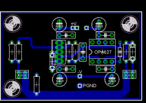
First of all, i see a serious fault. Before, you and I had the BW and V- pins on the BUF tied together but now when you have added option for a BW-resistor it seems that you have forgotten that the V- is actual pin 3. So if someone is using the BW resistor they will power the BW pin with the supply and the V- pin with the supply+resistor and if a jumper is used then you will have a pretty long V- trace and loosing the "100nF cap close to the pins"
Second, don't know if it's a problem but it seems that the route for the V+ to PGND has to go around the whole card and thru a 1mm wide trace close to the output resistor.
Keep it up!
 WoW didnt take long for thsi thread to pick up again.
This damn bandwidth resistor/cap has had me head scratching all day. I would rather use a SMD component but I know this would not be ideal for all, so I have tried to aviod it, but as I said it would be the preferred option.
The location of the resistor could be either on top with the buffer sitting or floating on top of it, or the preffered location would be to have it on the under side of the board.
To get anything better would require a major overhaul and the board would loose a lot of simplicity that a lot of people seem to like.
As for the route for the V+ to PGND, Russ disconected one of the ground supply in my original design with the two connector blocks, and there was no adverse effects as far as I am aware.
The ground plane will not be carrying a lot of current so I think the gap that is there is sufficient, but it could be increased if required.
Anyway here is the board with the BW resistor location.
I will ammend the other traces this is just to give you an idea of the location.
Anyway back to page 59 of the thread so i can catch up

Attachments
Nope, there was a few ppl, willing to contribute🙂WoW didnt take long for thsi thread to pick up again.
I think it would be a good idea to widen up the psu traces a bit, seems like there is room for it🙂
Steen😎
Hehe n00ber, that resistor is a p.i.t.*. 😀
I would say: skip it 🙂 if we were talking batterypowered headphoneamps..ok.
Oh and for that groundplane question n00ber i hope you didn't take it as a complaint. It was more like "i hope somebody can explain if it will work fine anyways" 🙂 because grounplanes isn't my cup of booze 🙂
I would say: skip it 🙂 if we were talking batterypowered headphoneamps..ok.
Oh and for that groundplane question n00ber i hope you didn't take it as a complaint. It was more like "i hope somebody can explain if it will work fine anyways" 🙂 because grounplanes isn't my cup of booze 🙂
It seems like everone is getting their TI samples, so the BW resistor might not be needed! If you use the TO220/ BUF634 you can safely run it in the widebandwidth mode. If it is adequately heatsinked!This damn bandwidth resistor/cap
I still live happy with, Macura's preamp-boards!
Steen.🙂
Ok heres my thoughts about the BW components.
I think the people that would be interested in swaping buffers, or tweaking the layout will obviously be more experinced, and there for would have no problems with smd components, and tbh they are not as much of a problem as people imagine, but we do not want to put people off.
Here is what I propose, I will revert back to he no resistor configuration, however I will add SMD pads.
This will allow the trace below the pads to be cut and a cap or resistor added or in the majority of cases totally ingnored.
I agree tobias that resistor is a MAJOR p.i.t.a 😉
I never took your comment about the GP as a complaint, im not entirley sure my self on this point, but when thinking of the currents involved I dont think it is an issue.
Fatter power traces comming up steen 😉
Hi N00ber,
I think you can safely ditch the BW resistor. I have been listening for a few days now, and do not miss it. Really as long the the buffer is heatsinked it is not necessary (I probably should not have mentioned it).
I wonder if you could turn that one decoupling cap on V+ at the buff 90 degrees do that it is oriented up and down. then move the electrolitic over to the right slightly. Viola, no more island (at least not one that matters), and no jumper.
It won't look quite as symmetrical, but who cares?
- Status
- Not open for further replies.
- Home
- Amplifiers
- Chip Amps
- GC Preamp Suggestions